
Guest Post, Author: Dr. Ardhendu Kundu (91-8240943188) | Senior Solutions Consultant – Simulation, Best Engineering Aids & Consultancies Pvt. Ltd. (BEACON) – Mumbai
In today’s world, high-power Radio Frequency (RF) sub-systems play a critical role in defence, space, aerospace, and telecommunication systems, where reliable generation, guided transmission and directive radiation of electromagnetic energy is essential for mission-critical operations such as surveillance, navigation, communication, and target tracking (RADAR detection). Systems such as ground based, drone borne and airborne radars, satellite payloads, electronic warfare platforms, and telecommunication links operate under extreme electrical, thermal, and mechanical conditions.In these critical environments, even small RF components can significantly impact the overall system performance and reliability.
Among the various RF components, high frequency low loss coaxial connectors are widely used due to their compact size, broadband performance, and ease of integration. However, in high-power RF operations, these high frequency connectors are often subjected to intense electromagnetic fields that lead to power losses (primarily in the form of heat energy), localized temperature hotspots, and structural deformation. These effects are indeed points of concern in critical operating conditions such as wide temperature variations, vibration, and long-term continuous operation in defence, space, aerospace and telecommunication systems. Failure of a single connector can result in signal degradation, significant power loss, or complete system failure – thus, robust design and analysing the electromagnetic, thermal and structural performances are absolute necessity for high power RF connectors. To meet the stringent and reliable performance standards for defence, space, aerospace, and telecommunication operations, advanced multiphysics analyses of RF connectors are necessary. Comprehensive electromagnetic–thermal–structural simulation using CST Studio Suite enables accurate prediction of field distribution, temperature hotspots, and structural deformation under high-power operations, providing valuable insight into potential failure scenarios. This integrated multiphysics approach using CST Studio Suite supports the development of highly reliable RF connectors (and other components in general), reduces costly and time-consuming operational iterations, and ensures safe and reliable operation in mission-critical electromagnetic system design.
Why Multiphysics Analysis of a RF Connector is Important – Technical Insights!
The reliable performance of coaxial connectors in high-power RF systems is governed not by electromagnetic behaviour alone, but by the strong unidirectional/bidirectional coupling between electromagnetic, thermal, and structural effects. At high power levels, in defence, radar, space, aerospace, and telecommunication systems, intense electromagnetic fields inside a coaxial connector produce conductive and dielectric losses that generate localized heating and temperature hotspots. This temperature rise further leads to thermal expansion and mechanical stress, and structural deformation of the connector geometry. Therefore, the impedance of the connector differs from the standard system characteristics impedance (50 Ω / 75 Ω) – such deformation and material degradation can further increase losses contributing to component overheating, mechanical failure or complete RF trans-receiver chain failure. Bidirectional multiphysics coupling enables evaluation of how heating and structural deformation in high frequency coaxial connectors influence their scattering parameters.
A comprehensive electromagnetic–thermal–structural analysis using CST Studio Suite enables a realistic evaluation of these coupled phenomena within a single simulation framework. By linking full-wave electromagnetic field distributions to thermal loss calculations and subsequent structural stress analysis, this approach allows engineers to identify hotspots, assess temperature limits, evaluate mechanical integrity, and determine safe operating power levels before physical prototyping. This methodology is especially important for high-power RF applications such as radar, satellite communication, and defense systems, where connector failure can compromise the entire system. Consequently, this work contributes to improved design optimization, enhanced reliability, reduced development cost, and a deeper understanding of multiphysics interactions in high-power RF components.
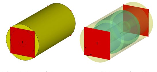
Coaxial Connector Modelling using CST Studio Suite and Simulation Setup The coaxial connector was modelled using CST Studio Suite, as shown in Figs. 1 and 2. The inner conductor, illustrated in Fig. 2, consists of a stepped-profile geometry (2mm-3mm-2mm radii) and is made of pure copper, whose electrical, thermal and mechanical properties are defined in the built-in CST material library. The cylindrical outer conductor is also modelled using pure copper with 9mm radius and 35mm length, as shown in Fig. 2. The intermediate dielectric layer is represented using a step-graded profile in terms of geometry as well as material properties.
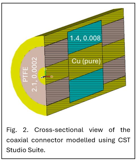
At Port 1, the dielectric is modelled using low loss PTFE with relative permittivity 2.1 and loss tangent 0.0002. In the central region, the dielectric properties transit to a material with relative permittivity 1.4 and loss tangent 0.008. Near Port 2, the dielectric layer is again modelled using low-loss PTFE (2.1, 0.0002). The thermal and mechanical properties of the dielectric materials were specified during material definition in the library. For the user defined dielectric material (1.4, 0.008), the thermal conductivity, Young’s modulus and thermal expansion coefficient have been set to 0.01W/K/m, 0.5GPa and 140*10-6/K respectively.
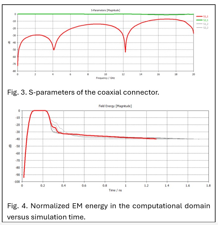
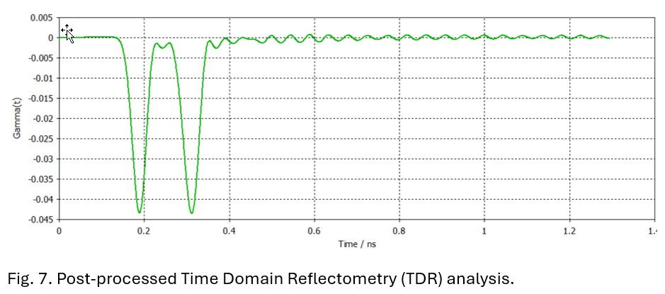
The electromagnetic simulation has been run over a broad frequency band up to 20GHz – all electromagnetic field monitors have been set at 7.5GHz. Since, Time Domain Reflectometry (TDR) study is required for evaluating the reflections at transitions – the higher frequency limit has been set to 20GHz for achieving a shorter pulse to resolve the inhomogeneity in the connector structure. Two waveguide ports have been defined at the two ends respectively Port 1 & Port 2, as illustrated in Fig. 1. Appropriate electric boundary (Et = 0) conditions have been defined – along with appropriate magnetic (Ht = 0) planes of symmetry to reduce the simulation run time. Furthermore, Port 1 & Port 2 have been considered to be symmetrical in terms of scattering parameters to further reduce the simulation time by another factor of 2. The time-domain solver was utilized with an accuracy of −40 dB, and a hexahedral meshing technique was adopted
Electromagnetic Analysis of the Coaxial Connector
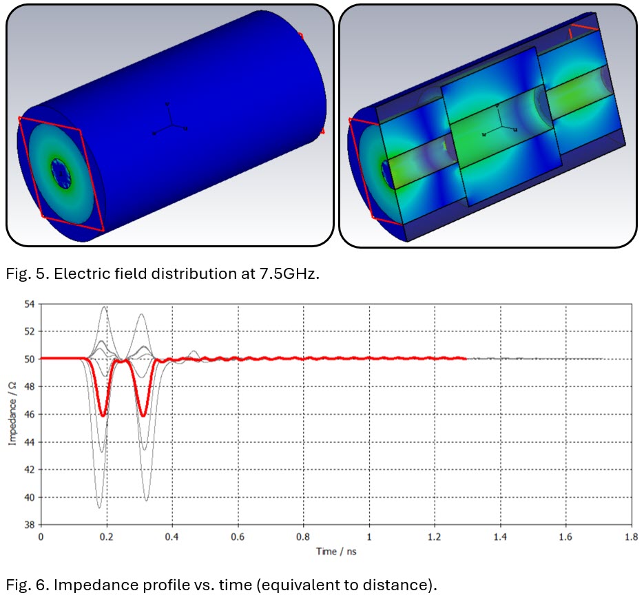
Following the electromagnetic simulation, the scattering parameters of the coaxial connector are presented in Fig. 3, showing the transmission and reflection coefficients at Ports 1 and 2. The energy plot in Fig. 4 illustrates the normalized electromagnetic energy in the computational domain versus simulation time, confirming that the −40 dB criterion has been met. For default 1W peak power in CST Studio Suite, the three- dimensional electric field distribution inside the coaxial connector is illustrated in Fig. 5. Furthermore, Figs. 6 & 7 respectively illustrate the impedance profile and TDR analysis results obtained using CST Studio Suite.
Read Part 02 — Continue Reading now

