
Guest Post, Author: Dr. Ardhendu Kundu (91-8240943188) | Senior Solutions Consultant – Simulation, Best Engineering Aids & Consultancies Pvt. Ltd. (BEACON) – Mumbai
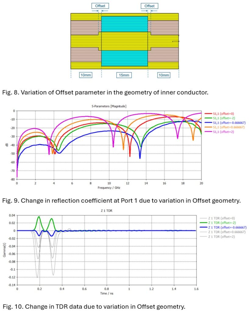
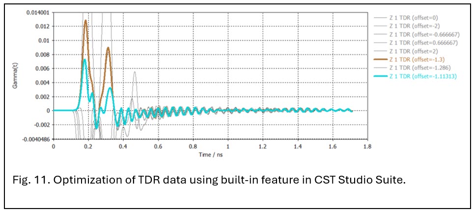
Fig. 8. illustrates variation of Offset parameter (-2mm to +2mm) in the inner conductor geometry – the corresponding variations in reflection coefficient data at Port 1 and TDR data have been recorded respectively in Figs. 9 and 10. Furthermore, built-in optimization tool in CST Studio Suite has been employed with a goal to reduce the maximum absolute value of reflection coefficient (in TDR) near to zero by tuning the value of Offset geometry between -2mm and -0.67mm. Figure 11 indicates an optimized Offset of −1.11 mm, with the maximum reflection coefficient close to zero, though slightly outside the defined limit.
Coupled Electromagnetic-Thermal Analysis of the Coaxial Connector
The classical thermal steady-state solver has been employed (THs) to simulate the coupled EM-thermal simulation for the coaxial connector structure. The primary advantage of thermal steady-state solver over conjugate heat transfer (CHT) solver in CST Studio Suite is simplicity and speed of simulation. In the connector structure, Offset geometry value has been set to -1.06mm – thereafter, unidirectional EM-thermal coupling project has been created. The losses at 7.5GHz in the electromagnetic simulation project have been imported to the coupled thermal solver for 1W peak (0.5W average) power. Since this work focuses on high-power RF system design and analysis, the losses at 7.5 GHz were scaled by a factor of 50 to simulate the temperature distribution and evaluate the thermal performance of the coaxial connector under 50 W peak (25 W average) operating power – please, refer to Fig. 12.
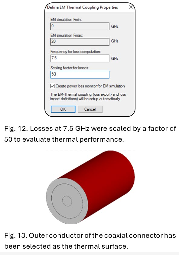
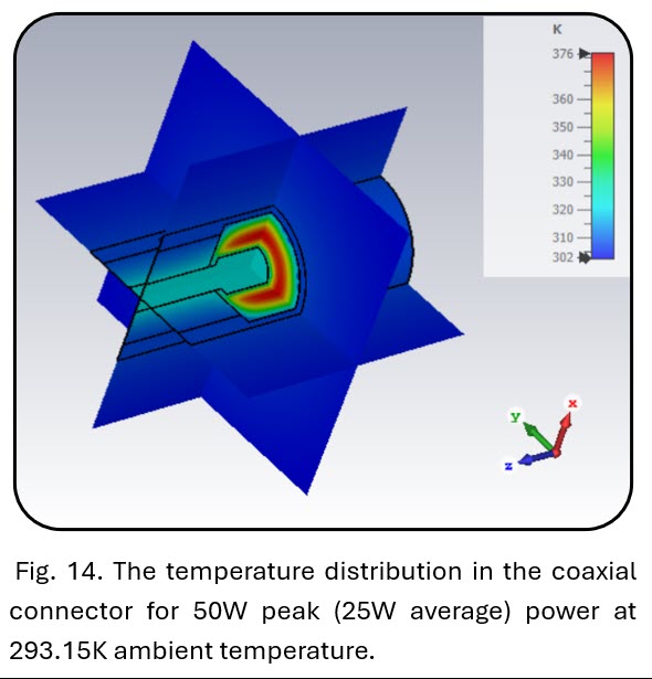
Appropriate thermal boundary condition has been defined in all the directions and background material has been set to air (CST Studio Suite material library). The outer conductor of the coaxial connector has been selected as the thermal surface – the convective heat transfer coefficient has been set to 20W/m2/K, as depicted in Fig. 13. The ambient temperature has been set to 293.15K (20 °C) during the thermal simulation. Fig. 14 demonstrates the typical temperature distribution inside the coaxial connector model under 50 W peak (25 W average) operating power. Data show maximum temperature rise to 376K (102.85 °C) in the intermediate dielectric layer of the coaxial connector with minimum temperature of 302K (28.85 °C) in the outer conductor. Hence, it is evident that the dielectric materials selected for fabricating coaxial connectors for high-power RF systems must withstand significant temperature rise during continuous operation in mission-critical surveillance, navigation, communication, and RADAR target-tracking applications.
Structural Analysis of the Coaxial Connector under Coupled EM–Thermal Loading
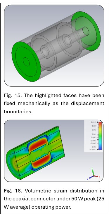
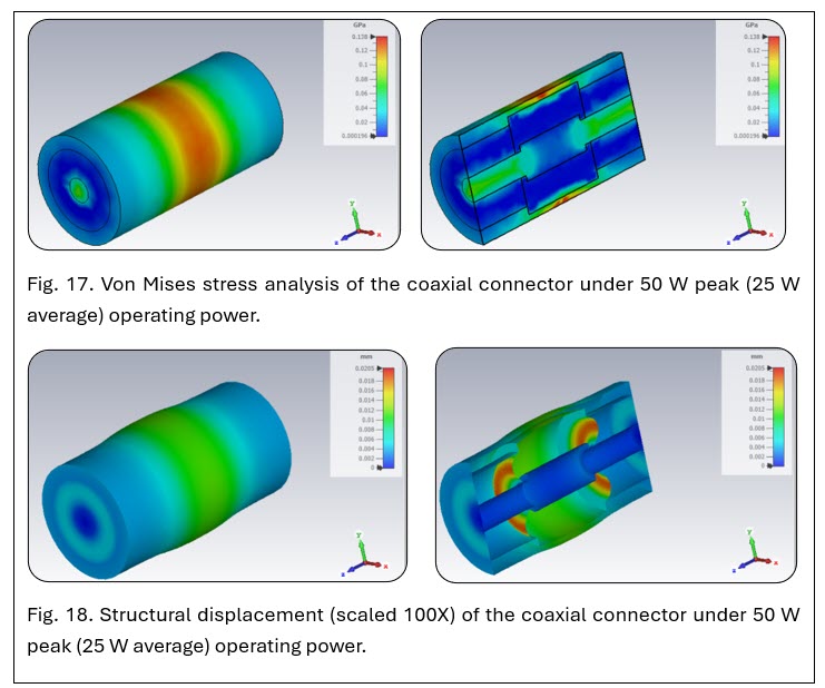
The structural integrity of the coaxial connector under 50 W peak (25 W average) operating power has been analyzed using CST Studio Suite. During the structural simulation, the evaluated temperature distribution has been imported as the source from the coupled EM-thermal simulation. In the structural simulation, the faces highlighted in Fig. 15 have been fixed mechanically to serve as displacement boundaries. It should be noted that the imported temperature distribution was directly applied in the structural simulation with a scaling factor of 1. Figs. 16 and 17 respectively illustrate volumetric strain and Von Mises stress distributions in the coaxial connector under 50 W peak (25 W average) operating power. The structural displacement of the coaxial connector under the abovementioned operating condition has been shown in Fig. 18 (scaled at 100X for better visualization) both on the outer surface and in different layers of the coaxial connector for high-power RF applications. The simulated data for the designed coaxial connector show the importance of structural analysis to choose proper metal and dielectric materials for high power operations in critical surveillance, navigation, tele-communication, and RADAR applications.
Conclusion This study demonstrates the importance of coupled electromagnetic–thermal–structural analysis of a coaxial connector designed for high-power RF operations in critical missions. Using the CST Studio Suite platform, the coaxial connector was modelled and analyzed under high-power operation (50W peak power in this simulation). Data reveal how electromagnetic losses generate localized heating that further contributes to
thermal expansion and structural displacement. The sequential multiphysics simulations using CST Studio Suite show that temperature rise in the dielectric and conductor layers can be significant and critical, with maximum temperatures reaching 376 K (102.85 °C) – emphasizing the need for materials capable of withstanding such thermal loads. Structural performance analysis further demonstrates the impact of thermal expansion on connector deformation. Data further confirm that even minor structural displacement can negatively impact impedance matching and can deteriorate overall RF system performance.
By integrating electromagnetic, thermal, and structural simulations, this work demonstrates the advantage of CST Studio Suite for reliable and robust design of high-power RF connectors – reducing the risk of failure by appropriate material selection to ensure safe and efficient operation in defence, aerospace, satellite and telecommunication applications. The demonstrated approach using CST Studio Suite establishes that accurate multiphysics evaluation is indispensable for achieving greater reliability and performance in high-power RF systems.
Acknowledgment of Technical Resources
The author would like to acknowledge the resources provided by Dassault Systèmes and Best Engineering Aids & Consultancies Pvt. Ltd. (BEACON) through the following websites, which were invaluable for both technical learning and the preparation of this blog on high-power RF coaxial connectors.
[1] www.3ds.com/products/simulia/cst-studio-suite
[4] https://beacon-india.com/blog
Thank you, BEACON India – SOLIDWORKS VAR, for the Guest Post

")
