Saturday, September 20, 2025
Home Blog Page 15

Registration Opens for Vectorworks Design Days 2025

COLUMBIA, MD, USA, Aug 11, 2025 – Global design and BIM software provider Vectorworks, Inc., will host its global Design Days again, inviting architecture, interior design, and landscape architecture and design professionals to these worldwide networking and educational events. Customers can connect with peers, explore emerging industry trends, and get a firsthand look at the latest features in Vectorworks 2026, launching September 2025.

“Design Days are about fostering a global community where designers can exchange bold ideas, explore cutting-edge tools, and shape the future of design,” said Vectorworks Senior Product Marketing Director Rubina Siddiqui, Assoc. AIA. “This year, we look forward to highlighting powerful updates and features that help architects, interior designers, and landscape professionals design more sustainably and creatively.”

Along with networking opportunities, attendees will hear success stories from industry peers and gain insights from Vectorworks senior leadership on the future of design and technology, including highlights from the Public Roadmap.

Vectorworks Design Days 2025 schedule:

  • Design Day London: October 14, 2025
  • Design Day Vancouver: October 30, 2025
  • Design Day Tokyo: December 5, 2025 (Architecture only)
  • Design Day Sydney: May 2026

Registration is free for each Design Day event. Prospective attendees can secure their spot through the registration page.

About Vectorworks, Inc.

Vectorworks, Inc. is an award-winning design and BIM software provider serving the architecture, landscape architecture and design, and entertainment industries in 85 countries. Professionals worldwide are using Vectorworks on Mac and Windows to create, connect, and influence the next generation of design. Built with designers in mind since 1985, Vectorworks software offers you the freedom to follow your imagination wherever it leads you. Headquartered in Columbia, Maryland, with offices in the UK, Canada, Australia, and Japan, Vectorworks is a part of the Nemetschek Group. Learn how you can design without limits at vectorworks.net or follow @Vectorworks.

PTC Appoints Jon Stevenson as EVP, Chief Product Officer, Digital Thread Portfolio

BOSTON, MA, USA, Aug 11, 2025 – PTC (NASDAQ: PTC) today announced that it has appointed Jon Stevenson as Executive Vice President, Chief Product Officer. Stevenson will be responsible for the strategy, development, and delivery of PTC’s Digital Thread product portfolio.

Stevenson brings more than three decades of experience in product development, engineering leadership, and technology innovation across CAD, PLM, AI, and SaaS. He previously held executive roles at Stratasys and GrabCAD and has more recently served as a board member, advisor, and investor to a variety of product development, SaaS, and AI-focused companies, including AllSpice, SimScale, Duro, nToplogy, and Vention. He previously served as a Vice President in PTC’s R&D Group and as the Executive Vice President of the company’s CAD business.

“Jon is an accomplished leader in our industry, and we’re thrilled to appoint him as Chief Product Officer,” said Neil Barua, President and CEO, PTC. “Jon’s technical and engineering expertise, proven leadership, and fresh perspective will help us accelerate priorities such as PLM and ALM integration, CAD, our transition to SaaS, and embedding AI across our product portfolio – all to help our customers achieve more.”

“It’s an incredible opportunity to serve as PTC’s Chief Product Officer,” said Stevenson. “We have the strongest product portfolio in industrial software and a great foundation for taking the next step in areas like SaaS and AI. I look forward to working with Neil and the leadership team as we continue helping our customers transform their businesses.”

Kevin Wrenn, PTC’s previous Chief Product Officer, is transitioning to a new leadership role within PTC’s product organization, focused on driving deeper customer engagement within the vertical-focused model announced at the start of the fiscal year.

About PTC

PTC (NASDAQ: PTC) is a global software company that enables manufacturers and product companies to digitally transform how they design, manufacture, and service the physical products that the world relies on. Headquartered in Boston, Massachusetts, PTC employs over 7,000 people and supports more than 30,000 customers globally. For more information, please visit www.ptc.com.

Undet Updates Point Cloud Plug-in for Ares Commander 2026

0

VILNIUS, Lithuania, Aug 11, 2025 – Undet is pleased to introduce Undet Suite 2026! The ultimate software suite for faster and cost-effective CAD deliverables. With the new annual release of Graebert ARES Commander 2026, we are glad to introduce updated version of Undet for ARES 2026. It is not only a compatibility update, but also a release of new version that contains great new features! By combining the powerful Undet add-on tools with ARES Commander CAD simplicity, we offer you an intuitive workflow to create 2D drawings based on precise as-built point cloud data quickly and easily.

Undet Suite combines the best of both worlds – powerful ARES Commander CAD software and Undet add-on ultimate point cloud toolset.

1. New user interface for faster workflow (tabs instead of workspaces)

Users no longer need to switch between workspaces to access Undet features like Floor Plans. Now you simply can go to Undet Floor Plans tab and get all the required features for annotating floor plans and other drawings. This simplifies the tasks of annotating drawings and has features more available with fewer clicks of a mouse button. 

2. 3D polyline tool improvement

It helps users to make sure the polyline you drawn sits at correct plane or surface intended in relation to your point cloud. Check selected points and polyline breakpoints, cutting the point cloud at each end. It will prompt you with a plan and section views to best identify where in the 3D workspace the polyline is located and how it is related to the point cloud. 

3. Auto stairs function

Auto Stairs streamlines the process of generating staircases in floor plans: it activates a line-based clipping operation that projects 3D stair data into accurate 2D plan geometry, saving you time and improving consistency in your plan drawings. Users can quickly convert 3D stair geometry into precise 2D plan graphics. It also ensures staircases are consistently visualized in plan views and automates the stair clipping process, reducing manual editing time.

4. Multi-room annotations

Floor Plan Room Height Annotation lets you accurately depict vertical dimensions (room heights, ceiling elevations, door heads, etc.) in your floor plans automatically, visually consistent, and easily customizable, improving both efficiency and presentation quality. It also allows to repeat it for all required rooms, hence making it multi-room.

5. Auto View section (levels) to generate floor plan sections fast

Auto View Sections simplifies the process of creating horizontal sections from point cloud data. Instead of manually setting clipping boxes, this tool automatically generates floor, cut‑plane, and ceiling views at predefined heights, ensuring accuracy and saving significant time in plan preparation. The Auto View Sections feature saves time by automatically creating horizontal sections at floor, cut‑plane, and ceiling levels, ensuring accuracy and consistency across all views. It improves visualization of architectural details, streamlines the workflow, and delivers clear, precise floor plan outputs with minimal manual effort.

6. Undet Quality Publish function

Now you can run an audit of your multi-floor plans making sure the quality of your drawings meets the requirements. It eliminates unnecessary viewports leaving just one, it purges your file of derelict items, deletes user created UCS’s. It also checks for critical issues and mistakes such as making sure the layer 0 is empty, there are 3D polylines, checks that Z or elevation coordinate of all objects is set to 0. It is a great new feature for quality assurance and control of your CAD project.

7. Coloring by logic class (automatic coloring for .las/.laz classified clouds)

Now you can color the point cloud based on logic classes. Coloring by logic class transforms your point-cloud view sections into meaningful, color-coded architectural diagrams. It enhances comprehension, classification checking, and visual communication—while being fully customizable and directly integrated into your workflow.

8. Bug fixes

Fixed multiple errors related to logic classes and point cloud exporting. Several other minor fixes are also included in this update.

To download, visit https://www.undet.com/online-store.

To know more about Undet products, visit https://www.undet.com.

Renishaw to Present New Smart Factory Innovations at EMO Hannover 2025

GLOUCESTERSHIRE, UK, Aug 11, 2025 – Global engineering technologies company, Renishaw, will demonstrate its latest innovations for process automation, closed-loop process control and rapid part verification at EMO Hannover 2025 (22-26 September). This includes an innovative new dual-method gauging system and dedicated gauging software.

The Renishaw technologies which will be on display at stand D06 in Hall 5 are renowned for addressing common global manufacturing challenges: to raise productivity and make high-precision parts more efficiently and cost-effectively.

Demonstrations will include industrial metrology and automation solutions for CNC machining and process control. All Renishaw technology provides a level of automation that eliminates the need for human intervention and skilled labour in CNC machining processes. This includes delivering unattended part set-up, closed-loop process control, and both machined feature and part verification at the point of manufacture.

Renishaw’s solutions make the integration of robots, metrology, and closed-loop process control for CNC machining easier, faster, and more effective. Eye-catching displays include process automation technologies integrated with commercially available robot handling systems for CNC machining and closed-loop process control, and automated CMM tending applications.

The company will also show its growing range of solutions for enhancing the accuracy and productivity of industrial robots. These technologies provide fast and easy robot set-up and robot cell recovery, as well as in-process metrology designed to improve the accuracy of automation cells.

Introducing the complete shop floor gauging solution

EMO Hannover 2025 attendees will discover Renishaw’s range of products for off-the-shelf integration with automation cells. This includes the new Equator-X™ 500 dual-method gauge and MODUS™ IM Equator software, which offer a complete gauging solution for shop floor processes.

The Equator-X system combines Absolute and Compare measurement functionality on a single device. High-performance measurement speed and accuracy also offer significantly improved inspection capacity and throughput compared to conventional 3-axis CMMs.

Supporting this hardware is the MODUS IM Equator software, with code-free programming and reporting capabilities. “The MODUS IM Equator software enhances the Equator gauging system,” says Rob Harrison, Renishaw’s Director of Industrial Metrology Software. “Empowering our customers to easily create inspection programs, allows them to harness the full potential of our metrology solutions.” Visitors can request a demonstration to experience the software’s ease of use and programming first-hand.

To expand the functionality of the Equator-X 500 system, Renishaw’s styli and modular fixturing accessories support a wide range of measurement tasks and help maintain high performance across different applications.

Next-generation machine tool probing

Also new for EMO 2025 is the third generation of Renishaw’s range of NC4+ Blue laser tool setters. Offering industry-leading repeatability at ±0.1 μm 2σ, the new ultra-compact F100 models redefine standards for high-speed tool measurement and broken tool detection. “At Renishaw, we strive to

develop technologies that make a meaningful difference to our customers,” says Steve Petersen, Marketing Manager of Renishaw’s Machine Tool Products Division. “The new third-generation F100 NC4+ Blue models exemplify this approach, combining sub-micron level precision with a compact, energy-efficient design.”

Making manufacturing easier

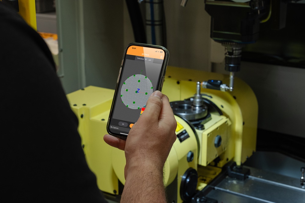
Another innovation for 2025 is a new smartphone app, which improves the user experience for Renishaw’s QC20 ballbar. The CARTO Ballbar Connect app makes it quick and easy for operators to complete valuable machine tool performance checks with minimal training. Dave Wall, Director and General Manager of Renishaw’s Laser Calibration Products Division says: “The CARTO Ballbar Connect app opens up the use of QC20 ballbar to a wider range of users who can now access the benefits of regular ballbar testing.”

Also supporting the reduced complexity of manufacturing is the simple-to-install FORTiS™ linear encoder. This exceptionally robust technology delivers high-performance measurement in the toughest machine tool environments. FORTiS encoders help to maintain machine accuracy over extended periods, making them ideal for automated ‘lights out’ manufacturing.

Data-driven manufacturing

A live demonstration of the Renishaw Central smart manufacturing data platform will connect data from the various measurement devices on the stand, including on-machine measurement, shop floor gauging systems, CMM inspection processes, and sensor data from the company’s leading additive manufacturing systems.

With Renishaw Central, issues can be identified, and machining and quality control systems can be updated automatically before the next part is machined, for real-time automated production. The Renishaw Central platform can digitalise, visualise, and act on manufacturing data, and provide greater visibility of parts as they move through the virtual factory.

The future of metrology is here

The ‘Innovate Manufacturing’ motto behind EMO Hannover 2025 embodies the spirit of innovation that drives Renishaw. To push the boundaries of what’s possible and demonstrate that the future of metrology is not just on the horizon – it’s here, now. By delivering fast, automated, connected, flexible, and easy-to-use manufacturing solutions, Renishaw’s technologies meet the evolving needs of modern manufacturers.

“The future of metrology is here,” states Rainer Lotz, President of Renishaw’s EMEA region. “People attend EMO to witness the best new innovations the industry has to offer, and we’re excited to be launching some truly ground-breaking technologies at the show this year.”

Join the Renishaw team on stand D06 in Hall 5 to see the latest innovations shaping the future of industry.

About Renishaw

Renishaw is a world leading supplier of measuring systems and manufacturing systems. Its products give high accuracy and precision, gathering data to provide customers and end users with traceability and confidence in what they’re making. This technology also helps its customers to innovate their products and processes.

It is a global business with over 5,000 employees located in the 36 countries where it has wholly owned subsidiary operations. The majority of R&D work takes place in the UK, with the largest manufacturing sites located in the UK, Ireland and India.

For the year ended June 2024 Renishaw recorded sales of £691.3 million of which 95% was due to exports. The company’s largest markets are China, USA, Japan and Germany.

Renishaw is guided by its purpose: Transforming Tomorrow Together. This means working with its customers to make the products, create the materials, and develop the therapies that are going to be needed for the future.

Further information at www.renishaw.com.

AML3D Commissioned ARCEMY X Metal AM System at Tennessee Public Utility Facility in US

EDINBURGH, Australia, Aug 11, 2025 – AML3D Limited (ASX:AL3) (“AML3D” or “the Company”) is pleased to announce the successful commissioning of the large scale ARCEMY X 6700 system (‘ARCEMY X’) for the Tennessee Valley Authority (‘TVA’). The TVA is federally owned and is the sixth-largest power supplier and largest public utility in the USA. The commissioning triggers payment of the final 10.5% of the circa A$1.972 million component of the ARCEMY contract with the TVA.

The TVA selected AML3D’s advanced manufacturing technology following a competitive tender process that assessed several options. The TVA’s ARCEMY X is the first system delivered from AML3D US Technology Centre located in Stow Ohio. The system is now operational at the TVA’s Muscle Shoals, Alabama service facility as part of the Utilities power generation repair fleet.

Delivery of the TVA ARCEMY X contract initiates the next phase of AML3D’s US Scale Up strategy, expansion into new industry sectors. At launch, in 2023, AML3D’s US Growth strategy focused on the US Defence sector and servicing the US Navy’s Submarine Industrial Base (‘SIB’). The successful deployment of ARCEMY technology into the SIB supply chain has resulted in a trebling of the US Defence opportunity into servicing the US Navy’s Marine Industrial Base (‘MIB’), which includes surface ships and munitions. The next phase of US growth includes further expansion into the US Utilities, Aerospace, Nuclear, Oil & Gas and Marine sectors.

AML3D CEO Sean Ebert said: “Delivery of the TVA ARCEMY X order is a strong endorsement of AML3D’s decision to focus on the US and our US Growth strategy. We were always confident we could springboard off our continuing success in supporting the US Defense sector to expand into additional US markets. The TVA contract marks our entry into the Energy and Utilities sectors and we are working hard to open opportunities across several other markets, including Aerospace and Oil and Gas. Even more exciting is the opportunity to use our US playbook to drive growth in the UK and Australia, the AUKUS defense partners and other globally significant markets.

President of AML3D US, Pete Goumas commented, “It is great to have successfully delivered the first ARCEMY system built at our recently opened Technology Centre in Stow Ohio. It’s also great to know that our advanced technology solutions won out when compared to alternatives as part of the TVA’s competitive tender process. We are up and running in Stow with huge opportunities to go after. We are becoming ever more embedded in the US Navy’s SIB supply chain. We have received a Letter of Intent, which highlights the key role for AML3D to support the US Navy MIB. That letter highlights the need for up to 100 ARCEMY systems and around 400 additively manufactured parts in 2026, rising to 1600 parts by 2030. Now, with our successful expansion into the US Utilities sector, we are starting on the next phase of our US growth, which includes accessing the US Aerospace, Oil & Gas and Marine sectors, to name but a few.”

About AML3D

AML3D Limited, a publicly listed technology company founded in 2014, utilizes new technologies to pioneer and lead metal additive manufacturing globally. Disrupting the traditional manufacturing space, AML3D has developed and patented a Wire Additive Manufacturing (WAM) process that metal 3D prints commercial, large-scale parts for Aerospace, Defence, Maritime, Manufacturing, Mining and Oil & Gas. AML3D provides parts contract manufacturing from its Technology Centre in Adelaide, Australia, and is the OEM of ARCEMY, an industrial metal 3D printing system that combines IIoT and Industry 4.0 to enable manufacturers to become globally competitive. For more information, visit https://aml3d.com.

Formlabs Form 4 & 4L : Redefining Precision in Large-Scale SLA 3D Printing

In this month’s newsletter, we’re excited to introduce updates, tips, and resources to help you unlock the full potential of your Formlabs Form 4 and Form 4L 3D Printers.

In the ever-evolving world of 3D printing, precision, versatility, and scalability are critical factors that set apart leading technologies. Formlabs, a pioneer in the 3D printing industry, introduces the Form 4 and 4L, a large-format SLA printer designed to meet the growing demands of professionals and industries seeking high-quality prints on a larger scale.

Form 4:

Unmatched Precision, Ultimate Versatility The Form 4 takes professional 3D printing to the next level. Engineered for accuracy and speed, it is perfect for producing prototypes and high-quality parts with fine details. The Form 4 combines industrial-grade technology with an intuitive design to meet the needs of professionals looking for reliable and scalable 3D printing solutions.

Form 4L:

Big Ideas, Bigger Prints Designed for large-scale projects, the Form 4L delivers the same high resolution as the Form 4 but with a significantly larger build volume. It’s perfect for creating bigger parts or increasing throughput without compromising on quality. With the Form 4L, you can take on ambitious projects and bring complex designs to life effortlessly.

FORM 4/ 4BFORM 4L /4BL
Technology Masked Stereolithography (MSLA)Technology Masked Stereolithography (MSLA)
Printer Engine Low Force Display™ (LFD)Printer Engine Low Force Display™ (LFD)
Build Volume (W x D x H)⁵ 20.0 × 12.5 × 21.0 cm
7.9 × 4.9 × 8.3 in
5.25 liters
Build Volume (W x D x H)⁵ 35.3 × 19.6 × 35.0 cm
13.9 x 7.7 x 13.8 in
24.2 liters
Light Source Backlight Unit: 60 uniform-wavelength LEDs, a plano-convex lens array, and integrated air cooling
405 nm optical wavelength
16 mW/cm² optical power intensity delivered to the cure plane
50 µm pixel size
Light Source Backlight Unit: 145 uniform-wavelength LEDs, a plano-convex lens array, and integrated air cooling
405 nm optical wavelength
16 mW/cm² optical power intensity delivered to the cure plane
46 µm pixel size
Resin Cartridges 1Resin Cartridges 2
Maximum Print Speed 100 mm/hour, 3.9 in/hourMaximum Print Speed 80 mm/hr, 3.1 in/hour
Materials 38 industry-leading Formlabs materials, including 15 biocompatible, or third-party materials using Open Material Mode. More exciting new materials are currently in development.Materials 32 industry-leading Formlabs materials, including 12 biocompatible, or third-party materials using Open Material Mode. More exciting new materials are currently in development.
PreForm File Types STL, OBJ, and 3MF file input
FORM file output
PreForm File Types STL, OBJ, and 3MF file input
FORM file output
Software PreFormDashboardFleet ControlSoftware PreForm, Dashboard, Fleet Control
Printer Weight 18.3 kg
40.4 lb
Printer Weight 58.5 kg
129 lb

Why Choose the Form 4L?

The Form 4L redefines what’s possible in stereolithography (SLA) 3D printing. It combines user-friendly design, exceptional material capabilities, and an expansive build volume, making it an ideal choice for those requiring intricate details in larger models or multiple smaller parts in a single print job.

Key Features of the Form 4L

  1. Large Build Volume

The Form 4L offers an impressive build volume, making it perfect for producing larger prototypes, detailed models, or multiple parts simultaneously. Its size unlocks opportunities for industries such as healthcare, engineering, and manufacturing to scale up their projects without compromising on quality.

  • Material Versatility

The Form 4L supports a wide range of materials, enabling users to choose the perfect resin for their specific application. From standard resins to specialty materials for dental, engineering, or biocompatible applications, the possibilities are endless.

  • User-Friendly Operation

Designed with ease of use in mind, the Form 4L features a streamlined workflow. Its intuitive software interface, remote monitoring, and maintenance-friendly design ensure seamless operation even for those new to large-format 3D printing.

  • Cost-Effective Production

By leveraging Formlabs’ robust ecosystem, the Form 4L reduces material waste and operational costs, making it an economical solution for scaling up production.

Applications of the Form 4L:

The versatility of the Form 4L makes it suitable for a range of industries:

Healthcare:   A pair of white skull models

Description automatically generated  
Create precise surgical guides, prosthetics, and anatomical models.          
Engineering:   A person holding a plastic container

Description automatically generated with medium confidence      
Build large prototypes or functional parts for rigorous testing.  
Education   A robotic hand on a desk

Description automatically generated
Enable students to explore large-scale projects and concepts.
Manufacturing   A close-up of several metal parts

Description automatically generatedProduce end-use parts, Molds, and tooling with ease.  

Transform Your Workflow with Form 4L:

Whether you’re an innovator pushing the boundaries of design or a business aiming to increase efficiency, the Formlabs Form 4L offers a robust solution for large-scale 3D printing. Its ability to deliver consistent, high-quality results across various applications makes it a game-changer in the industry.

To know more details, please reach out to us at:

Phone: +91 7406663589

Email ID: info@beacon-india.com

Website: http://beacon-india.com

Request a Quote Now: https://www.beacon-india.com/request-a-quote

Request a Demo Now: https://www.beacon-india.com/request-a-demo

How to Add Custom Part to SOLIDWORKS Toolbox Library

Guest Post by Mr. Mohammed Arbaaz Ahmed, Application Engineer, Hyderabad, BEACON

Designers often need to add custom parts to the SOLIDWORKS Toolbox for frequent use in company projects. These parts, which can be downloaded from various websites, should be saved in the shared Toolbox library. The SOLIDWORKS Toolbox includes thousands of standard hardware parts, but you can also add custom parts specific to your company. In this blog article, the steps for saving a custom file in the SOLIDWORKS Toolbox are demonstrated. Once added, these parts are easily accessible from the Toolbox in the Task Pane.

Preparing a custom part

  • Only SOLIDWORKS part files (.sldprt) can be imported into Toolbox. If the file was imported from another CAD system or is in a neutral CAD format, it must be saved as a SOLIDWORKS part file.
  • All configurations for custom part files must be manually entered and saved within the custom file. Toolbox does not have the ability to edit existing or create new configurations for custom parts.
  • All dimensions and characteristics must be manually entered and handled within the custom part file. Toolbox simply links to and works with the installation’s default files.
  • Custom properties must be defined and handled within the custom part file.

Inserting custom part to toolbox library

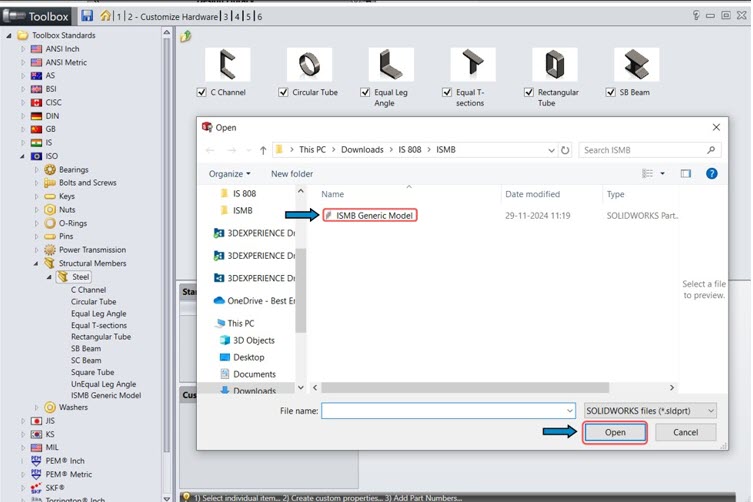
To add a custom part to SOLIDWORKS Toolbox, click the library tab, expand the Toolbox category, and then expand the SOLIDWORKS Task Pane on the right side of the SOLIDWORKS screen. Either click the Configure Toolbox bolt icon at the top of the Task Pane to open the Toolbox Configuration application, or right-click anywhere in the Toolbox and choose Configure Toolbox.

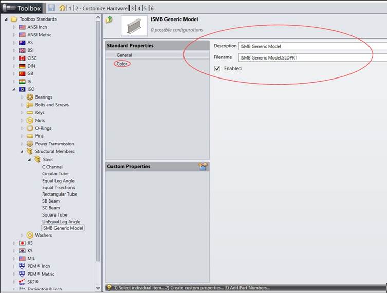
Use one of the following techniques to add a file or create a folder for the custom part under Toolbox Configuration, category 2 Customize your Hardware:

Right-click an existing standard and select ‘add file… .

Or

Choose “New Folder” from the menu when you right-click Toolbox Standards to make a new standard folder tailored to your business. The SOLIDWORKS Data folder will have a new standard folder created in it. Users must exit and restart SOLIDWORKS for the standard folder to appear in the Task Pane after adding a new standard.

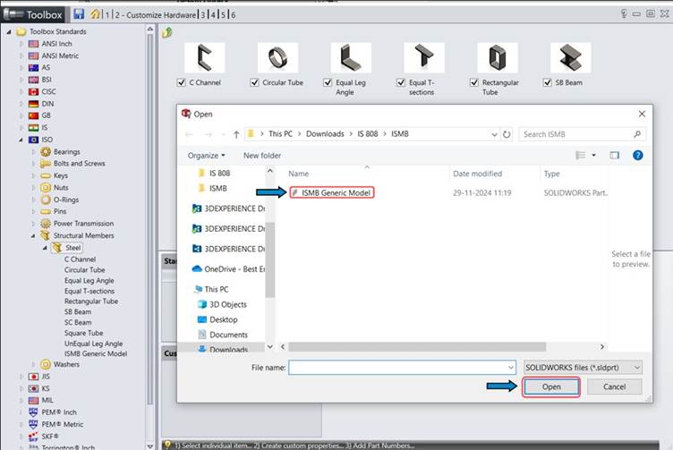
Next, choose “Add File” with a right-click on the newly formed folder. Add the necessary part file to the list by browsing to it. As needed, keep uploading more custom part files. Under the corresponding standard folder, new files are copied to the SOLIDWORKS Data folder.

Select a newly added part file by clicking on it. It is possible to change general settings like the part’s filename, description, and other unique attributes. It is also possible to change the part’s color settings (appearance).

You can now add your custom part to an assembly using the same drag-and-drop method as the Toolbox’s predefined elements.

Conclusion

Adding custom parts to the SOLIDWORKS Toolbox enhances design efficiency by making frequently used components readily accessible within the Task Pane. By properly preparing the part file and using the Toolbox Configuration tool, users can integrate company-specific or downloaded components into the Toolbox environment. This ensures consistency, saves time during assembly creation, and streamlines the overall design workflow in SOLIDWORKS.

Guest Post by Ahmed, Application Engineer, Hyderabad, BEACON

To know more details, please reach out to us at:

Phone: +91 7406663589

Email ID: info@beacon-india.com Website: http://beacon-india.com

Identifying Thermal Bottlenecks and Shortcuts in SOLIDWORKS Flow Simulation

Guest Post by Mr. Agastiya RV, BEACON, Technical Manager – Hyderabad

In any Electronic Enclosure, thermal management plays an important part of its design. The thermal design goal is to send the heat generated in the enclosure to the ambience. This can be achieved in many possible paths. In these paths, some of them can carry the heat easily and some other might develop a large resistance to the heat flow, due to the large temperature gradient, which creates a Bottleneck. This will also lead to the opportunity to introduce a Shortcut to the heat paths to avoid these bottlenecks.

The Bottleneck Bn and Shortcut Sc numbers are used primarily in electronics systems and other thermal systems. Hence, it’s a unique set of results that are exclusive for the Thermal Analysis in SOLIDWORKS Flow Simulation.

So, what exactly is a Bottleneck Number?

The Bottleneck number (Bn) identifies flow paths that carry high heat, while at the same time resist the flow of that heat. It is calculated by the ‘dot product’ of heat flux and temperature gradient vectors at any point.

Vector Notation:

Scalar Notation:

If the angle between the heat flux and temperature gradient is zero, then these two vectors are aligned with each other as it would be for conductive heat flow in a homogenous thermally isotropic material.

Vector Plot of Heat Flux and Temperature Gradient

The larger value of Bn is observed when:

  • The heat flux is large
  • And the temperature gradient is large
  • And the two vectors align with each other

The large Bn is also observed when the heat experiences a resistance in the direction of heat flow.

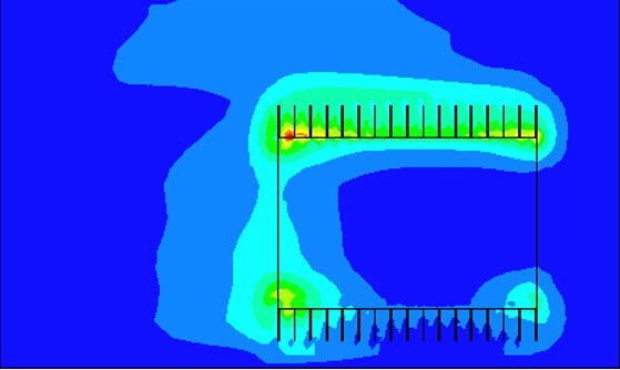
Bottleneck number Bn plot of a Heat Sink on a PCB

What is a Shortcut number?

The Shortcut number provides the opportunities for alternate and more efficient heat flow paths. It is calculated by the ‘cross product’ of Heat Flux and Temperature Gradient vectors at any point.

Vector Notation:

Scalar Notation:

If the heat flux and temperature gradient are orthogonal to each other, then Sc is simply the product of vector magnitudes. The temperature gradient is taken to be the indication of an opportunity to divert the heat to cooler areas.

The larger value of Sc is observed when

  • The heat flux is large
  • The temperature gradient is large
  • The two vectors are orthogonal

Large Sc is observed when the heat passes in parallel to a locally colder area.

Shortcut number Sc of a Heat Sink on a PCB

Both Bottleneck Bn and Shortcut Sc numbers provides tremendous insights to the importance of thermal design analysis and the graphical information on where the design improvements are needed.

Bn provides us a clear insight of the thermal bottlenecks and Sc provides the information on introducing thermal shortcuts in the design.

Unlike parametric studies, Bn and Sc data provides us the physical insight, helping every thermal designer to make the designs at a faster pace and effectively. The identification and using these fields in an electronics design offers the most promising thermal design modifications.

Guest Post by Mr. Agastiya RV, BEACON, Technical Manager – Hyderabad

To know more details, please reach out to us at:

Phone: +91 7406663589

Email ID: info@beacon-india.com Website: http://beacon-india.com

Renishaw to Launch 3rd-Gen NC4+ Blue Laser Tool Setters at EMO Hannover 2025

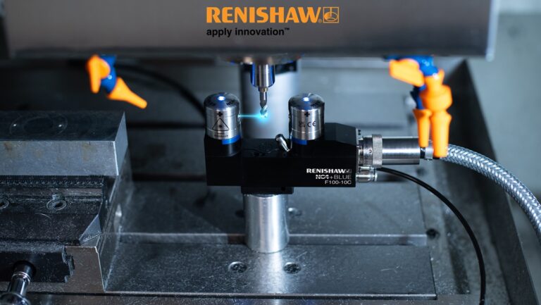
GLOUCESTERSHIRE, UK, Aug 8, 2025 – Renishaw, a global leader in high-accuracy measurement solutions, will launch its latest NC4+ Blue laser tool setter models at EMO Hannover 2025; hall 5 stand D06. Featuring third-generation technology, the new F100 and F100-10C models set a new standard for tool setting on CNC machine tools and reflect Renishaw’s commitment to advancing metrology for precision manufacturers.

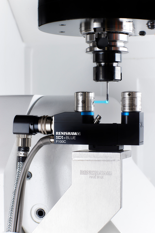
NC4+ Blue F100 on machine demonstrating tool measurement capability

With an optimised system design, NC4+ Blue F100 models achieve industry-leading repeatability of 0.1µ 2σ, ensuring exceptional precision for tool measurement. Tool features and defects as small as 5µ can be detected, allowing accurate measurement of ultra-fine tools and supporting even the most delicate machining operations. By identifying the smallest tool defects before machining, the systems help ensure a good surface finish, enhancing overall part quality.

A compact footprint makes the F100 models a perfect fit for machines with tight working envelopes, allowing manufacturers to optimise space while maintaining high-performance tool setting capabilities.

Renishaw has enhanced the efficiency and optimised the air flow in the NC4+ Blue F100 models. It has reduced the tool setters barrier air consumption by over 50%, reducing the required energy for air compression, lowering operational costs for manufacturers. This advancement reflects Renishaw’s continued commitment to improving the sustainable performance of its products.

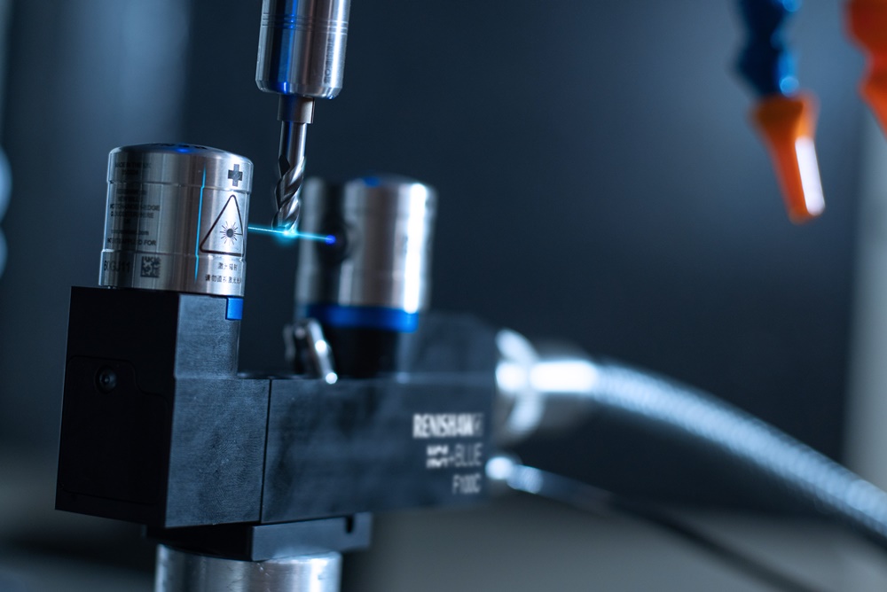
Renishaw’s third-generation NC4+ Blue laser tool setter F100 model on machine measuring tool with laser beam

As part of Renishaw’s NC4+ Blue laser tool setter portfolio, the F100 models are designed to deliver high-precision, high-speed non-contact tool setting and tool breakage detection. Featuring industry-first blue laser technology, all NC4+ Blue systems detect tool defects down to micron levels, aiding the production of ‘right first time’ parts. The NC4+ Blue MicroHole aperture and PassiveSeal mechanism protect the system in harsh environments, guaranteeing reliable performance even under challenging conditions.

“At Renishaw, we strive to develop technologies that make a meaningful difference to our customers. The new 3rd gen F100 NC4+ BLUE models exemplify this approach combining sub-micron level precision with a compact, energy-efficient design. These systems help manufacturers achieve consistent quality while reducing operational costs, reinforcing our commitment to excellence in metrology.” commented, Steve Petersen, Product Management and Marketing, Machine Tool Division.

Renishaw’s advanced macro software for the NC4+ Blue allows manufacturers to automate tool measurement and set-up processes. With a wide range of non-contact tool setting cycles, manufacturers can streamline operations, increase efficiency, and achieve consistently high-quality results.

Explore the latest in non-contact tool setting at EMO Hannover 2025, hall 5 stand D06, from 22nd to 26th September and speak tothe Renishaw team about how they can support your manufacturing goals. For more information on the NC4+ Blue and Renishaw’s full product range of metrology products, visit www.renishaw.com.

About Renishaw

Renishaw is a world leading supplier of measuring systems and manufacturing systems. Its products give high accuracy and precision, gathering data to provide customers and end users with traceability and confidence in what they’re making. This technology also helps its customers to innovate their products and processes.

It is a global business with over 5,000 employees located in the 36 countries where it has wholly owned subsidiary operations. The majority of R&D work takes place in the UK, with the largest manufacturing sites located in the UK, Ireland and India.

For the year ended June 2024 Renishaw recorded sales of £691.3 million of which 95% was due to exports. The company’s largest markets are China, USA, Japan and Germany.

Renishaw is guided by its purpose: Transforming Tomorrow Together. This means working with its customers to make the products, create the materials, and develop the therapies that are going to be needed for the future.

Further information at www.renishaw.com.

Aconity3D’s Business Case Calculator Simplifies Part Cost Calculation for Additive Manufacturing

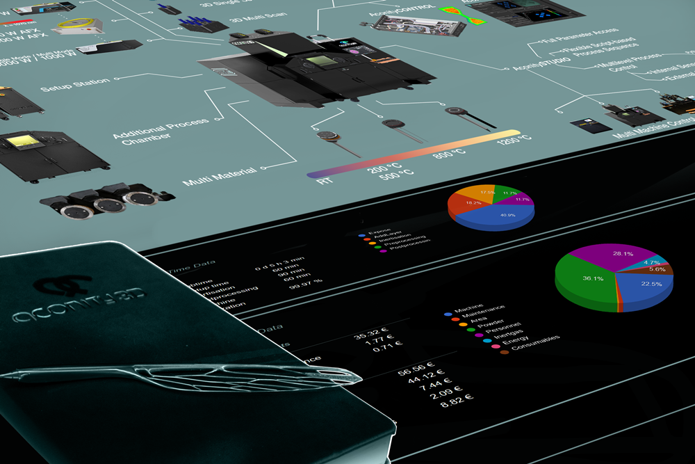
HERZOGENRATH, Germany, Aug 8, 2025 – Aconity3D is pleased to introduce Business Case Calculator to help users find the most cost-efficient Aconity3D machine. Aconity3D’s Business Case Calculator is a powerful software tool designed to help users analyze part costs and uncover significant savings potential in additive manufacturing projects.
Based on users specific application requirements, the tool also identifies the most suitable and cost-efficient Aconity3D machine configuration, but at its core, it’s all about enabling user to make informed, cost-driven decisions.

How it works – in just three steps:

1. Your Application

Upload your CAD file, specify the material, and define your desired batch size.

2. Your Production Environment

Enter key operational parameters such as depreciation, available floor space, space and energy costs, personnel structure, auxiliary systems, and shift setup.

3. The Result: Part Cost, a Breakdown of Time and Expenses, and the most Cost-Efficient Machine Configuration

Using your data, the tool calculates part costs and highlights the key contributors. This reveals the most effective levers to further reduce manufacturing costs. Additionally, the tool suggests the machine configuration that offers the best performance-to-cost ratio for your specific use case.

For more information, visit https://aconity3d.com.