REDMOND, WA, USA, Jun 9, 2025 – ActCAD 2025 New update 1310496 released based on latest IntelliCAD 13.1 engine. This is a general maintenance release with below mentioned fixes and improvements:
Several improvements to Network Licensing and implemented Client time-out feature
Introduced LAYOUTWIZARD for guided creation and setup of layout tabs
Added new COUNT command and its subcommands to automatically count and list entities in drawings
Introduced CENTERREASSOCIATE to re-associate centerlines and centermarks with geometry
Added PKFSTGROUP for managing fast selection groups
Introduced XBIND to bind external references with control over symbol table items
Added UCSMAN for easier user coordinate system management
Introduced NEWVIEW to create and manage named views within the drawing
Added CDORDER command to control draw order of entities based on color
Introduced TIFOUT for exporting drawings to TIFF format
Added OLERESET to reset OLE objects within the drawing
Introduced BLOCKICON to update preview icons for blocks
Added right-click menu options for all entities
Fixed issues with the BlockAttributeEditor command
Fixed issue where drawing names were incorrect on exit
Introduced a new NLM timeout feature for improved license usage flexibility
Introduced default new drawing opening with + button (without dialog)
Improved product activation mechanism
Fixed issues related to PDF2DXF functionality
Fixed issue with the COUNTTABLE command
Introduced new system variables ACTPLOTLEFTTOPPT and ACTPLOTRIGHTBOTPT to store click points in a drawing
Added Preview highlight functionality in the Print command
Resolved issue where no message appeared for incorrect selection in EDITDATAEXTRACTION command
Fixed crash that occurred during block creation by handling windows in the UI thread
Corrected table alignment issues that affected sorting behavior
Resolved problem where associative hatches couldn’t be stretched after COPYCLIP–PASTECLIP
ActCAD brings Global Collaborated Technology Expertise to you at very affordable life-time price. ActCAD is powered by the most latest IntelliCAD 10.1a engine, Open Design Alliance Tiegha Libraries and ACIS technologies. ActCAD has many enhancements, features and commands on top of IntelliCAD core. The add-on features, express menu commands allow ActCAD to become more productive for day-to-day projects. ActCAD works very closely with IntelliCAD on Development and Quality Assurance. Thanks to our highly automated test and build systems to keep our costs minimal. IntelliCAD was started in 1999 and has over 1 million trusted users now using IntelliCAD world-wide. ActCAD is a commercial member with active role in Release Committee and Board of Directors of IntelliCAD. For more information, visit http://actcad.com.
Formlabs has recently introduced Tough 1500 Resin V2, an upgraded version of their engineering-grade photopolymer designed for stereolithography (SLA) 3D printing. This new formulation offers significant enhancements over the original Tough 1500 Resin V1, making it more suitable for demanding applications that require a balance of strength, flexibility, and durability.
Key Improvements in Tough 1500 Resin V2 Enhanced Toughness and Impact Resistance: Tough 1500 is engineered to absorb impacts better than its predecessors. This improvement makes it a preferred choice for parts that might be subject to stress, impact forces, or even repeated mechanical loading. Although exact numerical specifications (for tensile strength, flexural modulus, or elongation at break) should be referenced against Formlabs’ technical data sheets, the material is positioned to bridge the gap between standard photopolymer resins and more robust engineering plastics.
Mechanical Strength: The resin offers a balanced combination of rigidity and ductility. This means that while the printed parts are strong and capable of sustaining load, they also exhibit a degree of flexibility that prevents sudden catastrophic failure—a particularly valuable trait when simulating injection molded parts or creating assemblies that need to endure real-world handling.
Print Process Compatibility: Tough 1500 is optimized for use with Formlabs’ SLA (stereolithography) systems. It typically prints with a high degree of dimensional accuracy and consistency, and it is designed to be amenable to standard post-curing processes. This ensures that once printed and fully cured, the parts manifest the enhanced mechanical properties promised by the material’s formulation.
Comparative Advantages: In comparison to the earlier “Tough” or even “Durable” resin offerings from Formlabs, Tough 1500 is targeted at applications where even greater mechanical resilience is required. Its improved performance can help reduce the risk of fracture in dynamic environments, potentially extending the lifecycle of functional prototypes.
Ideal Applications Tough 1500 Resin V2 is particularly well-suited for: Prototypes requiring the toughness and resilience of polypropylene. Rugged enclosures with functional elements like snap fits and self-tapping screw bosses. Impact-resistant jigs and fixtures for long-term use on the factory floor. Parts that need a combination of stiffness and ductility, such as compliant mechanisms like latches, flexures, and dampers These properties make Tough 1500 Resin V2 a versatile material for applications requiring a balance of strength, flexibility, and durability
Conclusion Formlabs’ Tough 1500 Resin represents a significant step forward for additive manufacturing materials aimed at functional and end-use applications. Its enhanced toughness and ability to absorb impacts make it a compelling option for designers and engineers who require a material that can endure stress without sacrificing detail or print resolution.
Abaqus is a powerful finite element analysis (FEA) software widely used in engineering and scientific communities to simulate complex physical phenomena. While the software offers extensive built-in capabilities, certain advanced analyses require customization beyond the standard features. This is where Abaqus subroutines come into play. Subroutines are user-defined code snippets, typically written in Fortran, that allow users to define their own material behavior, boundary conditions, loading scenarios, element formulations, and other specialized features. They provide the flexibility needed to model complex, nonlinear, or user-specific behavior that cannot be captured through Abaqus’s default settings. This write-up explores the various types of Abaqus subroutines, their applications, and the workflow for implementing them in a simulation environment. Abaqus subroutines support FORTRAN, C, C++, etc.
Abaqus consists of two sets of subroutines. Abaqus standard subroutines which are utilized in static to implicit dynamics procedures whereas explicit subroutines are used for explicit dynamics steps. Some of the important subroutines and their significance are mentioned below.
DFLUX
DFLUX subroutine can enable a moving heat flux source. This is most suitable in case of welding simulation where moving heat source is required. The heat source can be given as a function of time, position or temperature etc. An example is shown below.
DLOAD
DLOAD subroutine allows you to simulate moving loads. The load can be varied based on time, position or temperature etc. The scenarios such as moving vehicle loads on a road or bridge, dynamic loading in aircraft can be simulated with the aid of DLOAD subroutine. An example is shown below (displacement with respect to load).
UEL
The UEL subroutine in Abaqus allows users to implement their own finite element formulations by defining the element’s stiffness matrix, residual vector, and other element-level behavior. It is used when standard Abaqus elements cannot capture the required physics or numerical approach, such as in advanced materials, multiphysics problems, or novel element types. UEL is often used to model fracture propagation in rock formations using cohesive elements or extended finite element methods (XFEM). Engineers implement custom fracture mechanics algorithms to simulate crack initiation and growth during hydraulic fracturing operations.
UMAT
UMAT is a user-defined subroutine in Abaqus that allows engineers to implement custom material models by defining the stress-strain behavior, internal state variables, and evolution laws under various loading conditions. It is widely used in the aerospace industry to simulate the complex, nonlinear, and often anisotropic behavior of advanced composite materials in structures such as aircraft wings and fuselages, where standard material models are insufficient.
UGENS
UGENS enables users to define the general section behavior of beam elements by customizing the stiffness, coupling effects, and nonlinear responses of cross-sections. This subroutine is commonly applied in civil engineering, particularly for simulating non-standard or composite beam sections in bridge decks, tall buildings, or towers, where interaction between bending, shear, and torsion must be captured accurately.
UMESHMOTION
UMESHMOTION is used to control the movement of the finite element mesh in simulations involving deforming geometries or moving boundaries, typically in Arbitrary Lagrangian-Eulerian (ALE) or coupled fluid-structure interaction problems. It finds important industrial applications in processes such as blow molding of plastic containers and simulating the dynamic motion of oil tankers over ocean waves, where mesh motion must follow physical boundaries precisely.
The subroutines used in Abaqus Explicit are like above. The difference is that explicit time integration will come into picture (new and old-time steps) and names will be changed in such a way that VDLOAD, VDFLUX, VUMAT etc.
In 3DEXPERIENCE Fluid Dynamics Engineer, the multispecies model enables the simulation of fluid flows involving two or more chemically distinct substances, such as air and water vapor, fuel-air mixtures, or contaminant dispersion in air. This model captures the transport and mixing of individual species within a single-phase flow, accounting for differences in properties like molecular weight, diffusivity, and specific heat. The framework allows for the specification of boundary conditions for each species (e.g., mass fraction or inflow composition), making it suitable for a wide range of applications, from HVAC airflow analysis to combustion precursors and microfluidic mixture making.
The multispecies capabilities in 3DEXPERIENCE are tightly integrated into the finite volume-based solver, and include options for species transport equations, diffusion modeling, and source terms such as volumetric mixture source. Users can monitor species concentration fields, track scalar transport, and perform post-processing on quantities like total mass fraction or mixing efficiency. The model also allows coupling with thermal and turbulent models, enabling realistic simulation of heat and species transfer in complex geometries. This makes it a powerful tool for industries requiring accurate prediction of mixing, dilution, or contamination, such as automotive, aerospace, energy, and packaging.
One of the main applications of multispecies models comes in microfluidic mixtures which are extensively used in the medical field. Water-ethanol, water-glycerol are some of the unique examples for different medicine preparation. Y shaped mixture channels are the most used mixing channels for these applications. As indicated by arrow marks in figure below the individual fluid (water and ethanol) comes through the inclined limbs, get mixed at the center of the channel and flow out through the other limb. The size of square cross section channels are 6 μm respectively. The simulation results are also given below.
The results shows proper flow development after mixing (see velocity contour).
The flow development (fully developed velocity) happens after mixing as visualized from velocity contour. The mass fraction of Ethanol is at initial and final (1s) are shown in the contour below.
The ethanol from left limb mixes with water from the right limb at the center. Mass fraction of 0.5 is seen at center (mixing region). This implies that proper mixing is achieved on the channel. The mixing region is developing a rectangular sheath at channel center. This sheath is important in field of nanoparticle generation.
In short, the multispecies model in 3DEXPERIENCE Fluid Dynamics Engineer offers a reliable and efficient way to simulate the transport and mixing of multiple non-reacting fluid species within a single-phase flow. While it does not support chemical reactions, it accurately captures the spatial and temporal variation of species concentrations due to convection and diffusion. This makes it particularly valuable for a wide range of applications such as gas dispersion, ventilation analysis, air quality prediction, and microfluidics—where precise control of species mixing and transport at small scales is critical. By integrating with thermal and turbulence models, the multispecies capability provides a comprehensive approach to understanding and optimizing fluid behavior in complex geometries, supporting better engineering decisions across industries including aerospace, automotive, packaging, biomedical, and microfluidic system design.
The NC Shop Floor Programmer is a foundational role within the 3DEXPERIENCE platform designed to simplify and accelerate programming of 2.5-axis and 3-axis milling machines, along with 2- and 4-axis wire EDM machines. Serving as an entry-level machining solution, it empowers manufacturing engineers and NC programmers to generate precise 3D parts through an intuitive and immersive digital environment.
At its core, the software offers a realistic virtual workspace where users can efficiently setup workpieces, assemble cutting tools, and simulate toolpaths to validate machining strategies before production. This simulation-driven approach helps detect potential collisions and material removal issues early, reducing costly errors on the shop floor.
Seamlessly integrated with 3DEXPERIENCE SOLIDWORKS and cloud services, NC Shop Floor Programmer enhances collaboration by connecting design and manufacturing data, ensuring digital continuity throughout the process. Users benefit from guided workflows, automated feature recognition, and cloud-enabled resource access, supporting fast, standardized, and reliable NC programming in modern manufacturing environments.
Core Features and Functionalities
NC Shop Floor Programmer delivers a robust suite of capabilities tailored to streamline programming for 2.5-axis and 3-axis milling as well as 2- and 4-axis wire EDM machines. Central to its functionality is the Setup Wizard, which guides users through configuring workpieces and tools within a realistic 3D environment, dramatically reducing setup time and simplifying complex machine preparation.
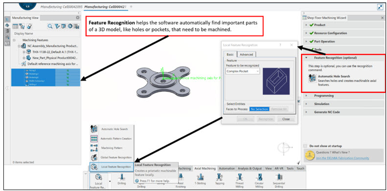
Complementing the setup process, intuitive toolpath creation wizards assist programmers in defining operations like pocketing, contouring, roughing, finishing, and probing. These wizards feature context-sensitive menus and dynamic help icons that offer quick visual explanations, enabling even less experienced users to navigate options confidently without interrupting workflow.
A key productivity enhancer is the software’s automatic prismatic feature recognition, which detects machining features directly from part geometry. This functionality automatically generates a manufacturing view listing all drill holes, pockets, and milling areas, allowing rapid generation of tailored toolpaths without manual feature definition.
For 3-axis milling, NC Shop Floor Programmer incorporates advanced machining strategies covering the full spectrum from roughing to finishing. Users can select from high-efficiency approaches such as helical or spiral roughing and precision finishing strategies including deburring or Z-level contouring. The software continuously analyzes tool assemblies and stock material during operation sequencing to produce optimized, collision-free toolpaths.
The built-in toolpath simulation module offers detailed visualization of material removal and machine motion, enabling early identification of collisions, gouging, or remaining stock irregularities. Programmers can quickly verify or edit toolpaths, thus preventing costly errors on the shop floor and ensuring efficient machining cycles.
Wire EDM programming is fully supported with dedicated 2- and 4-axis operation modes. Users can define synchronized wire paths and simulate cutting sequences to verify complex contours. The solution also enables reuse of wire EDM strategies through templates, facilitating consistency and reducing programming effort for repetitive setups.
Throughout the interface, context-based menus and interactive help panels provide a responsive and user-friendly experience. Illustrations dynamically update as parameters are adjusted, fostering better understanding and decision-making without requiring extensive training or reference to external documentation.
Advanced Simulation, Verification, and Automation
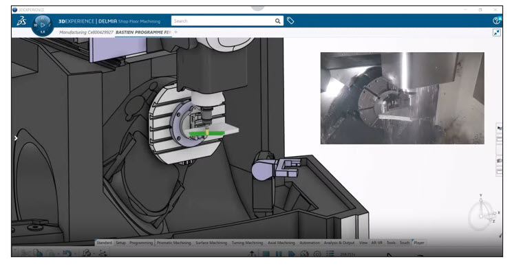
NC Shop Floor Programmer excels with its state-of-the-art 3D toolpath simulation capabilities that immerse NC programmers in a highly detailed virtual machining environment. This simulation faithfully reproduces the entire machining process, enabling users to visualize every movement of the cutting tool relative to the workpiece. Programmers can scrutinize simulated material removal, detect gouges and collisions early, and verify the correctness of tool changes and machine kinematics before any actual machining takes place.
The platform’s collision detection highlights risk such as tool interference or near-misses at user-defined safety thresholds, helping prevent costly and dangerous errors on the shop floor. Additionally, the material removal simulation provides precise analyses of the remaining stock throughout operation sequences, empowering programmers to optimize cutting strategies and reduce unnecessary machining passes.
Beyond visualization, NC Shop Floor Programmer integrates powerful automation and standardization tools through reusable templates and knowledge-based rules powered by Knowledgeware. Users can capture best practices and company-specific expertise in templates that automatically apply machining parameters based on part features, significantly accelerating programming workflows while ensuring process consistency.
Reusable templates: Store and recall optimized machining processes to reduce redundant programming efforts.
Knowledgeware objects: Enable intelligent automation by associating machining logic and constraints directly to NC programming elements.
Batch processing: Leverage background computation of toolpaths to maximize user productivity without workflow interruption.
Together, these simulation, verification, and automation features empower NC programmers to produce error-free, collision-free, and efficient toolpaths within a comprehensive 3D contextual environment. This robust validation framework significantly reduces programming risks, shortens development cycles, and boosts manufacturing throughput by delivering precise, optimized machining operations every time.
The 2025 update of NC Shop Floor Programmer introduces several cutting-edge improvements aimed at boosting user productivity and streamlining machining workflows. A redesigned, dedicated user interface now simplifies searching for machines, cutting tools, and accessories by integrating favorites and search history, enabling faster access to frequently used resources and reducing setup time.
Machine movement optimization between machining operations has been enhanced with an automatic path calculation feature. This intelligent system respects machine kinematics and collision avoidance, including advanced handling of tool rotations via Rotate Tool Center Point (RTCP) control. Users gain real-time visibility of toolpath costs and tool life warnings in the process tree, helping to plan more efficient and safer machining sequences.
A significant productivity boost comes from the introduction of AI-guided machining cycle recommendations. Leveraging neural networks trained on typical geometries and operations, this assistance guides both novice and experienced users in selecting optimal machining strategies—such as pocketing, contouring, or drilling—based on proven best practices.
The update also introduces robust support for multi-part setup management, enabling machining of grouped components in one run to maximize machine utilization. Enhanced simulation reliability is achieved through automatic detection and removal of floating material chunks, preventing false collision alerts and improving confidence in material removal validation.
Additional workflow acceleration is provided by a new batch mode for toolpath computations, allowing background processing of lengthy calculations while users continue other tasks uninterrupted. Furthermore, a nesting command optimizes placement of multiple parts on raw material blocks, reducing waste and increasing material utilization efficiency.
Together, these enhancements empower NC programmers with intelligent assistance and workflow automation, driving faster programming cycles, reducing errors, and supporting higher throughput on the shop floor.
NC Shop Floor Programmer delivers substantial time savings by leveraging an intuitive interface equipped with setup wizards and context-sensitive menus, allowing programmers—regardless of experience—to rapidly generate accurate NC programs. By minimizing idle machine motions and optimizing toolpaths, it effectively maximizes machine tool utilization, boosting production throughput while lowering operational costs.
Its comprehensive 3D virtual machining environment intricately models tools, cutters, and machine kinematics, enabling early detection of collisions or toolpath inefficiencies to mitigate production risks. This immersive simulation ensures reliable and safe machining, reducing scrap and rework.
Furthermore, seamless integration within the 3DEXPERIENCE platform fosters collaboration across teams and promotes intellectual property reuse via templated machining strategies. Precise, up-to-date NC code generation supports digital continuity, enhancing both quality and cost efficiency in real-world manufacturing environments.
NC Shop Floor Programmer stands as a vital tool within the 3DEXPERIENCE ecosystem, empowering users to achieve exceptional precision and efficiency in milling and EDM programming. By fully leveraging its advanced setup wizards, feature recognition, simulation, and automation capabilities, manufacturers can streamline workflows and enhance collaboration across teams.
MCKINNEY, TX, USA, Jun 6, 2025 – Sigmetrix, announced their latest release of CETOL 6σ tolerance analysis software, version 12.1, is now available for immediate download. Tolerance analysis benefits businesses in many ways. It helps improve profitability by balancing quality with manufacturing cost. Companies can also realize faster time to market by reducing the need for additional design and prototype cycles. Finally, it allows companies to gain confidence in their product and process decisions before making costly investments.
CETOL 6σ enables product development teams to understand the often-complex impact of dimensional and assembly variation easily and fully on their designs. This knowledge enables them to make the proper adjustments before problems appear in manufacturing or, even worse, in their customers’ hands. This new release of CETOL 6σ builds upon the powerful features already in place and adds many improvements, including:
Improved support for patterns per ISO GPS standards, including correct application of the Combined Zone (CZ) modifier and correct referencing of patterns establishing datum in Datum Systems. This extends to annotations created in Creo and NX files by CETOL.
Enhancements to ease the definition of Joint controls, including:
Improved automated Joint DOF settings when importing assembly constraints.
Simplified tools to orient joints for fasteners and alignment pins.
Ensuring users define specific directions when biasing joints between cylindrical features of size.
Tools to help users easily understand Assembly State assignments of Parts, Subassemblies, and Joints.
Support for Projected Tolerance Zones.
Improved support for Inseparable Assemblies, including:
Import CAD assembly constraints referencing features within Inseparable Assemblies.
Import & link to assembly-level annotations.
Create assembly-level annotations based on tolerances defined in CETOL for Creo and NX.
Notification when the model becomes “Not-Closed” after adding new joints that create conflicting definitions.
CETOL model “roll-back” bar similar to that found in several CAD systems.
For the NX-Integrated version:
Import assembly constraints to create joints.
Annotation Creation for NX allowing users to automatically define Product Manufacturing Information (PMI) from tolerances defined in CETOL.
As with prior releases, CETOL 6σ v12.1 is available in English, Japanese, and Simplified Chinese.
Sigmetrix Director of Customer Success and Product Strategy, Stephen Werst, commented:
“CETOL 6σ v12.1 is yet another significant step forward for Sigmetrix as we strive to achieve feature parity across all supported CAD platforms, continue to make the software easier to use, and extend CETOL from just an analysis tool to one that can help make better design decisions as early in the process as possible. This release, along with improvements in our entire product portfolio, continues our unrelenting efforts to help companies build better products through mechanical variation management via a robust combination of software, training, and consulting services.”
If you’d like to see a demo of the newest version of CETOL 6σ in action, make sure to be on the lookout for on our LinkedIn page for a webinar announcement.
Sigmetrix’s comprehensive, integrated portfolio includes other products and services including:
CETOL 6σ, a 3D tolerance analysis solution for Siemens NX, SOLIDWORKS, PTC Creo Parametric, and CATIA V5-6.
EZtol, a 1D tolerance analysis solution for Siemens NX, SOLIDWORKS, and CATIA V5-6 models. The same technology is used in PTC Creo’s EZ Tolerance Analysis (EZTA) tool and Autodesk Inventor’s Tolerance Analysis tool.
VariSight, provides enterprise-level management of mechanical variation data, facilitating continuous improvement and optimization across the entire design and manufacturing process.
GD&T Advisor, an interactive tool that provides expert guidance on the correct application of GD&T within the PTC Creo Parametric and Autodesk Inventor environments.
Training provided through more than a dozen instructor-led and computer-based courses covering basic to advanced ASME GD&T, ISO GPS, tolerance analysis, and our software products.
Consulting and implementation services team with collectively over 200 years of experience in dimensional management offers a variety of consulting services to augment your design teams as well as to identify root causes of, and solutions for, variation-related issues impacting your production costs and quality.
About Sigmetrix
Sigmetrix has been helping companies produce better products for over 20 years through a combination of software solutions, training, and consulting services that focus on managing the impact of mechanical variation. For more information, visit their website at https://www.sigmetrix.com.
LUCERNE, Switzerland, Jun 6, 2025 – BETA CAE Systems is thrilled to announce the bug-fix version 24.1.6, for ANSA, EPILYSIS, META, KOMVOS, and FATIQ.
Known issues resolved in ANSA
Shell Mesh
The behavior of “Checks > Penetration:Proximities” has been significantly improved; now it can recognize proximities with both sides of baffles and interior boundary conditions.
Known issues resolved in EPILYSIS
Keywords
RESVEC and AUTOSPC commands were not parsed, in case they appeared first in header.
Known issues resolved in META
LS-DYNA
*LOAD_NODE_POINT keyword with variable from *PARAMETER_EXPRESSION would not be read correctly.
Managing Curve Data
Bending Moments were not read from dcfail output.
NVH Calculators
Focusing on FRF Assembly, response curves in TPA window were not highlighted when a path was selected.
Known issues resolved in KOMVOS
Configuration
Unlike prior versions, it is now possible to seamlessly configure DM-relative paths for templates, for both File-based and SPDRM, for both Logbook and Overview Report, and save the configuration in the KOMVOS.defaults settings file.
Download
Where to download from
Customers who are served directly by BETA CAE Systems, or its subsidiaries, may download the new software, examples and documentation from their account on our server. They can access their account through the “download” link on our website. Contact us if you miss your account details. The Downloads menu items give you access to the public downloads. Customers who are served by a local business agent should contact the local support channel for software distribution details.
What to download
All files required for the installation of this version reside in the folders named “BETA_CAE_Systems_v24.1.6”, “KOMVOS_v24.1.6” and “FATIQ_v24.1.6” and are dated as of June 4, 2025. These files should replace any pre-releases or other files downloaded prior to that date. The distribution of this version of our pre- and post-processing suite is packaged in one, single, unified installation file, that invokes the respective installer and guides the procedure for the installation of the required components.
For the installation of the software on each platform type, download from the respective folders, the .sh file for Linux or the .msi file for Windows.
In addition to the above, optionally, the META Viewer is available to be downloaded for each supported platform.
The tutorials and the example files reside in the folder named “TUTORIALS”. This folder includes a complete package, and one with only the updated files.
The Abaqus libraries required for the post-processing of Abaqus .odb files are included in the installation package and can be optionally unpacked.
Earlier software releases are also available in the sub-directory called “Previous_Versions” or in a folder named after the product and version number.
About BETA CAE Systems
BETA CAE Systems is a private engineering software company committed to the development of state of the art CAE software systems that meet the requirements of all simulation disciplines. The company’s products, the ANSA pre-processor/ EPILYSIS solver and META post-processor suite, and SPDRM, the simulation-process-data-and-resources manager, hold a worldwide leading position across a range of industries, including the automotive, railway vehicles, aerospace, motorsports, chemical processes engineering, energy, electronics, heavy machinery, power tools, and biomechanics.
Committed to its mission to produce best-in-class CAE software systems, BETA CAE Systems offers products that consistently exceed expectations and provides exemplary technical support to its customers. The company’s continuously growth attest to the high level of customer satisfaction and user confidence. For more information, visit http://www.beta-cae.com.
ST. PETERSBURG, Russia, Jun 6, 2025 – ASCON Group, the leading Russian developer of high-performance CAD/AEC/PLM systems, is pleased to announce that, it will exhibit at ACMEE 2025 – India’s Premier International Machine Tool Show—on 19-23rd June at Chennai Trade Center, Nandambakkam, Chennai, in Tamilnadu.
ACMEE is India’s leading biennial exhibition on Machine Tools, Automation and Industrial Technology, organized by AIEMA (Ambattur Industrial Estate Manufacturers Association). The exhibition places strong emphasis on emerging technologies such as Automation, Robotics, IoT, Industry 4.0, Artificial Intelligence and Digital Manufacturing. Intended to demonstrate cutting-edge technologies and innovative solutions in the manufacturing sector, ACMEE brings together top international players. This year, ASCON will present its KOMPAS-3D software as a part of Automation and Robotics exhibition.
Meet ASCON from 19th to 23rd June 2025 at Chennai Trade Centre, Hall H “Automation and Robotics”, booth H107. We look forward to welcoming potential partners, clients, industry experts, CAD consultants, design engineers, universities representatives, and many more! Come to visit us at our stand!
About ASCON
Founded in 1989 as a private company, ASCON, becoming one of the first CAD/AEC/PLM developers and integrators in Russian and CIS member countries. Its software solutions address key engineering design issues, such a accurate 3D modeling, preparation and release of drawings and design documentation, business process development, and engineering data management.
Today, ASCON is a dynamic company employing 800 highly qualified specialists. The company operates 60 offices and dealer centers in major industrial regions worldwide. Each branch office provides a full range of services in software implementation, IT consulting, personnel training, software integration and support.
The number of KOMPAS installations exceeds 80 000 seats in automotive, heavy machinery, aerospace and defense, agriculture, oil production and power generation, manufacturing and construction, electronics and engineering industries. For more information, visit https://ascon.net.
SEOUL, South Korea and NEW DELHI, India, Jun 6, 2025 – Hyundai Motor Group (the Group) announced the opening of the Hyundai Center of Excellence for future mobility technology (Hyundai CoE) at the Indian Institute of Technology (IIT) Delhi.
This initiative is establishing a joint research system to advance future mobility technologies focused on electrification and battery systems, reflecting the Group’s commitment to driving innovation tailored to the needs of Indian customers.
The Group has selected nine joint research projects in collaboration with IITs as part of its long-term academic-industrial cooperation framework. These projects cover key focus areas including:
Battery cells, systems and testing
Battery management systems (BMS)
Energy density enhancement
Safety
Durability
Diagnostic technologies.
The initiative also explores new materials and system components, driving forward innovation in battery design and performance.
Hyundai Motor Group officials – including Heuiwon Yang, President and Head of the R&D Division; Unsoo Kim, Managing Director of Hyundai Motor India Limited; and Chang Hwan Kim, Executive Vice President and Head of the Electrification Energy Solutions Tech Unit – attended the main agreement ceremony held in New Delhi. They were joined by IIT representatives, including Prof. Rangan Banerjee, Director of IIT Delhi; Dean Manu Santhanam from IIT Madras; and Dean Sachin C. Patwardhan from IIT Bombay.
The Steering Committee of the Hyundai CoE will be co-chaired by EVP Chang Hwan Kim and Dean Bijaya Ketan Panigrahi at IIT Delhi.
“We’re excited to work with India’s brightest minds in battery innovation,” said Heuiwon Yang, President and Head of R&D Division at Hyundai Motor Group. “Collaborating with leading researchers and IIT professors through the Hyundai Center of Excellence for future mobility technology will help us develop technologies tailored to India while contributing to its economy and society. We see this partnership with India’s academia and industry as a foundation for building a sustainable future together.”
Future Technology Research
In parallel, the Group is expanding its Future Technology Research Program, which has been in operation since 2021. Unlike the general operation methods of academic-industrial projects, the program allows university faculty members to propose their own research topics, which are then reviewed and selected by the Group.
Previously limited to domestic universities and Korean professors at overseas institutions, the program has been expanded to include foreign faculties – beginning with professors at IITs. This marks a significant step in globalizing the Group’s academic collaboration efforts.
Starting with IIT Delhi, the Hyundai CoE will expand in phases to build an India-wide network of experts, connecting leading researchers and institutions across the country.
Currently, the Group collaborates with three IIT universities (IIT Delhi, IIT Bombay, and IIT Madras), engaging around 30 professors. By December 2025, it aims to expand its reach to 10 universities in India, including non-IIT institutions, with approximately 100 professors participating.
The Group is organizing a range of initiatives to further strengthen this collaborative ecosystem. These include:
Technology exchange forums bringing together experts from both India and Korea
Global conferences on battery and EV technologies to share insights on trends and policies
Policy dialogue sessions that engage key stakeholders from the Indian government, academia, and industry to discuss the future of the mobility and electrification sectors
As the Group’s first academic-industrial collaboration model for a growth economy, the Hyundai CoE is set to become a central hub for research and innovation. It will play a key role in advancing future mobility solutions while fostering a strong, localized innovation base tailored to the evolving needs of the Indian market.
Autodesk has launched the ‘BIM Package for Viksit Bharat’—a customised suite of Building Information Modelling (BIM) tools designed specifically for India’s public sector. This tailored solution enhances design accuracy, streamlines workflows, and supports national development goals through localized compliance and automation features.
New Delhi, June 5, 2025 – Autodesk, has announced the launch of customised design technology solutions for the public sector in India. In a pioneering move, Autodesk has introduced India-focused Building Information Modelling (BIM) suite – ‘BIM Package for Viksit Bharat’, a ready-to-deploy digital solution, designed specifically for India’s engineers, architects, and policymakers, aligning with India’s Viksit Bharat ambitions. The solution was unveiled by Ashish Kumar Mittal, Director of Public Sector, Autodesk India & SAARC and Ashish Kumar Mittal, Alok Sharma, Director, Architecture, Engineering and Construction (AEC), Autodesk India & SAARC, at the Autodesk Viksit Bharat Summit in New Delhi, highlighting the critical role of digital tools in achieving national development objectives. The initiative reiterates Autodesk’s commitment to empower the design and make industries globally.
The newly launched India-focused BIM suite includes India-based countrification toolsets for two premier Autodesk solutions—Autodesk Revit and Autodesk Civil 3D. Revit, tailored for architects, structural engineers, and MEP professionals, now integrates Indian-standard components and templates based on the latest Delhi Schedule of Rates (DSR). This customization will help streamline the design process for residential and commercial buildings, reduce rework, and enhance collaboration across disciplines. The Civil 3D offering, designed for civil engineers and infrastructure consultants, adheres to Indian Road Congress (IRC), Ministry of Road Transport and Highways (MoRTH), and Indian Railways standards (IRS), enables faster, more accurate road and rail designs with automated features that significantly reduce manual effort.
“BIM is much more than a design tool – it is the digital backbone of infrastructure delivery. However, BIM adoption in India has often been challenged by the lack of tools aligned with local design codes, construction norms, and workflows. The India-focused solutions are built specifically to address these gaps, simplifying the adoption of BIM at scale and helping stakeholders across the ecosystem deliver better, faster outcomes in line with Indian standards and requirements.” said Alok Sharma, Director, AECO, Autodesk India & SAARC
“India’s infrastructure ambitions are among the most expansive in the world, with large-scale investments underway in urban development, transportation, housing, and industrial corridors. In such a dynamic environment, BIM will continue to play the critical role in enabling precision, efficiency, and transparency for designers and innovators in the Architecture, Engineering, Construction and Operations (AECO) segment.” Sharma added.
The launch of Autodesk’s BIM Package for Viksit Bharat comes at a time when India’s infrastructure and construction sectors are rapidly embracing advanced technologies including AI, Generative Design and Digital Transformation to meet growing demands for scale, speed, and sustainability. As per Autodesk’s 2025 State of Design & Make report, 52% of Indian organisations are already using AI to drive sustainability outcomes, well above the global average. It signals an industry shift toward smarter, AI-enabled tools that reduce waste, minimize errors, and help deliver infrastructure that is both future-ready and environmentally responsible. Autodesk’s customised BIM solutions are built to support this momentum offering India-specific capabilities that help fast-track project delivery while aligning with national development goals.