Thursday, September 18, 2025
Home Blog Page 4

Form 4 or 4B: Unmatched Speed, Accuracy, and Reliability to Redefine 3D Printing.

Guest Post by BEACON India – Formlabs Re-seller India

Form 4 represents the next evolution in SLA 3D printing, built upon years of groundbreaking hardware, software, and materials science innovations. With unprecedented speed, Form 4 delivers the majority of parts in under two hours, in all materials, without ever compromising on dimensional accuracy or surface finish.

Stunning Parts: Rivaling injection molded parts.

Blazing Fast: Most prints in under 2 hours

Versatile: Industry-leading materials for any problem

Intuitive: Anyone can learn in 15 minutes

Reliable: Unmatched print success rate
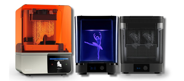
Explore the Hardware of the Formlabs Form 4 or 4B Printer:

  • Backlight

The Backlight Unit generates a uniform area projection of an ultra-high power light using 60 LEDs and collimating lenses. It cures resin quickly and precisely, delivering blazing fast print speeds with excellent print quality and accuracy anywhere on the build platform.

  • Light Processing Unit

The Light Processing Unit 4 (LPU 4) precisely masks light from the backlight unit into the shape of a printed layer. Together, the Backlight Unit and LPU 4 enable you to print with extreme speed, accuracy, and print quality anywhere on the build platform. The LPU 4 is long -lasting, resistant to accidental damage, and easy to replace.

  • Release Texture

A proprietary, microtextured optical film provides airflow between the resin tank and the Light Processing Unit. This film is built into the Light Processing Unit and sits at the top of it. This significantly reduces peel forces so you can print at blazing fast speeds without sacrificing surface finish, fine features, accuracy, or reliability.

  • Intelligent Control Systems

Six onboard control systems precisely measure and maintain the temperature, resin level, print forces, and print status inside your printer. Together, they ensure consistent, reliable performance and prevent common failures, for the same results on every printer and every print.

  • Resin Tank

The Form 4 Resin Tank holds liquid resin inside the printer and provides a substrate for the liquid resin to cure against, using a dual-layer flexible film stack. It significantly reduces peel forces so you can print at blazing fast speeds without sacrificing surface finish, fine features, accuracy, or reliability.

  • Automatic Resin Handling

Integrated system that dispenses resin quickly, accurately, and with minimal waste, while making it easy to switch materials. Print without having to worry about your printer running out of resin and switch materials in <1 minute. Form 4 is still one of the only SLA printers on the market to offer this feature.

We hope you found it informative and inspiring. Stay tuned for future updates, and don’t hesitate to reach out with any questions or feedback.

Happy Printing!

Guest Post by BEACON India – Formlabs Re-seller India
Dive into Motion: Analysing a 4-Bar Assembly in 2D Sketch with SOLIDWORKS Motion

Guest Post by Mr. Nikhil M, Sr. Application Engineer. BEACON India

In mechanical design, understanding how components move is essential. With SOLIDWORKS CAD Premium and SOLIDWORKS Simulation solutions, Motion Analysis lets us simulate and study this behaviour, offering valuable performance insights. In this blog, we’ll explore a 4-bar linkage using a simple 2D sketch—a fast, efficient way to grasp core kinematics without the complexity of 3D models.

What is a 4-Bar Linkage?

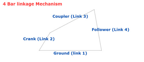
A four-bar linkage is a fundamental mechanical system composed of four rigid links connected by four revolute joints (hinges). One of these links is fixed, serving as the ground link, while the others move in relation to it. By varying the lengths of the links, you can achieve a wide range of output motions, making this mechanism a crucial component in many machines. Common applications include windshield wipers, certain suspension systems, and foldable chairs.

The Importance of Blocks in 2D Motion Analysis

For SOLIDWORKS Motion to recognize the individual parts of a mechanism, you need to use blocks. A standard 2D sketch won’t work because all the lines are treated as one rigid body, preventing you from defining motion between them.

Here’s why blocks are essential:

  • Isolate Components: Blocks allow you to define each part of your mechanism as a separate, movable body.
  • Create a Virtual Assembly: By treating each component as a block, you can make a 2D sketch behave like a true assembly with defined motion.
  • Enable Motion Analysis: SOLIDWORKS Motion needs these individual “links” to identify and analyse their relative movement.

Setting Up Your 2D Sketch with Blocks

This is the key to a successful 2D motion analysis. You’ll create a 2D assembly using blocks in Layout.

  1. Sketch Your Assembly: Start by drawing the first link of your 4-bar assembly, for example, the crank
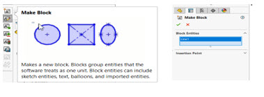
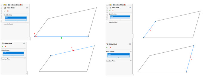
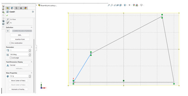
  2. Create the Block: Select all the sketch entities that make up this first link. Then, go to Tools > Block > Make Block. This converts the selected entities into a single block. You’ll be prompted to define an insertion point, which is the point that will serve as the pivot for a revolute joint.

3. Repeat for All Links: Repeat this process for each of the other three links in your 4-bar assembly. You will now have four distinct blocks representing your four links.

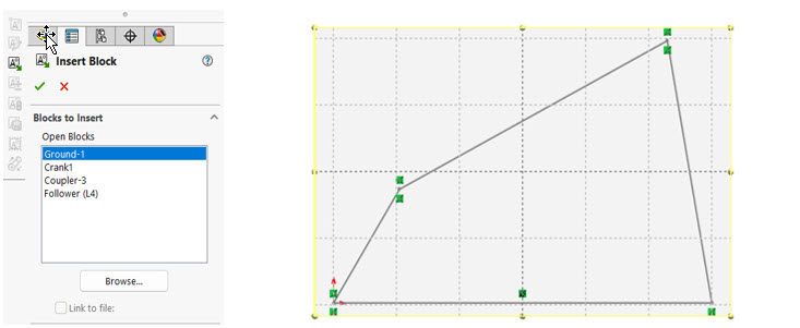
4. Assemble the Blocks: Create a new assembly use standard sketch relations like Coincident to “assemble” the blocks at their pivot points, just as you would with a physical assembly.

5. Setting Up Mass Properties for Motion Analysis in SOLIDWORKS

When preparing a Motion Analysis study, accurate mass properties are essential for realistic results. By default, SOLIDWORKS assigns estimated mass and moment of inertia values to each block, treating it as a uniform steel block with the center of mass at its geometric center. You can fine-tune these properties in the Block Property Manager.

  • Automatic Estimates: Each block in your layout sketch is assigned default mass and moment of inertia values, based on a uniform steel block.
  • Center of Mass Defaults: By default, the center of mass is positioned at the geometric center of the block.
  • Full Control: You can override these defaults to match real-world materials, shapes, or custom weights.
  • Simple Editing: Adjust the mass, center of mass, and moments of inertia directly in the Block Property Manager under Mass Properties.

Why It Matters: Accurate mass data ensures your Motion Analysis captures real-world dynamics — from smooth operation to predicting peak loads.

Bringing it to Life with SOLIDWORKS Motion Once your 2D sketch is set up with blocks and constraints, it’s time to leverage the power of SOLIDWORKS Motion:

  1. Access SOLIDWORKS Motion: Navigate to Tools > Add-Ins and ensure that SOLIDWORKS Motion is checked.
  2. Create a New Motion Study: Go to the “SOLIDWORKS Motion” tab and click on “New Motion Study.”
  3. Define the Motion Analysis Type: In the Motion Study properties, select “Motion Analysis.”
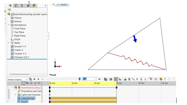
  4. Add Forces and Springs: You can add forces and springs to drive the mechanism. Use the Force feature to apply a vertical load to a specific point on a link. Use the Spring feature to connect two points on different links to simulate a spring’s effect, defining its stiffness and free length.
  5. Set Simulation Parameters: Define the Analysis time and frames per second in the Motion Study properties.
  6. Run the Simulation: Click the “Calculate” button. SOLIDWORKS Motion will now simulate the movement of 4-bar linkage.

Analysing the Motion and Reaction Forces

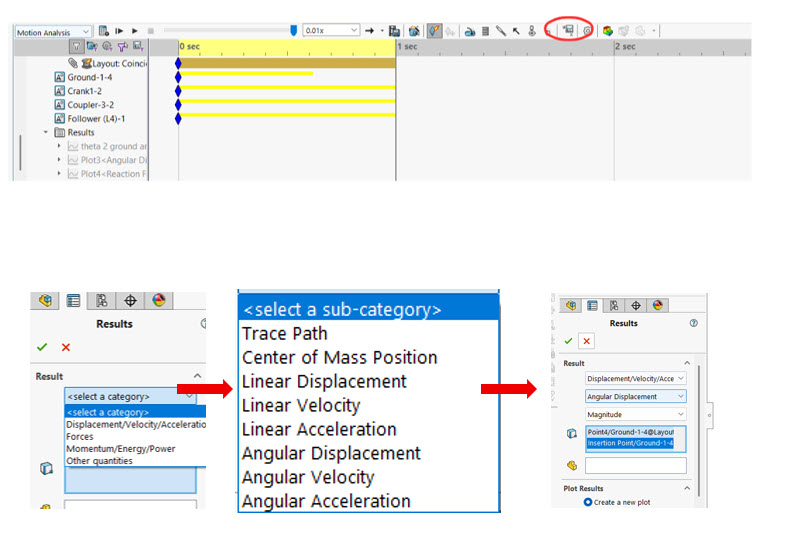
Once the simulation is complete, the real insights begin. SOLIDWORKS Motion AnalysisResults and plots” option allows you to plot various parameters, including:

  • Angular Displacement, Velocity, and Acceleration:
  • Linear Displacement, Velocity, and Acceleration:
  • Reaction Force vs. Angular Displacement:

The Benefits of 2D Motion Analysis

While 3D simulations offer more visual richness, analysing a 2D sketch provides several key advantages:

  • Simplicity and Speed: Setting up a 2D motion analysis is faster and less computationally intensive.
  • Focus on Core Kinematics: It allows you to concentrate on the fundamental motion relationships between the links.
  • Early-Stage Design: It’s an excellent tool for quickly evaluating different linkage configurations early in the design process.

Conclusion

Simulating 2D sketch with SOLIDWORKS Motion Analysis by defining components as blocks is an effective way to learn kinematics and explore motion simulation. Even simple sketches can come alive, delivering valuable insights into mechanical behaviour.

Author

Guest Post by Mr. Nikhil M, Sr. Application Engineer. BEACON India

To know more details, please reach out to us at:

Phone: +91 7406663589

Email ID: info@beacon-india.com Website: http://beacon-india.com

Trimble Initiates FedRAMP Authorization for Connected Construction Solutions

WESTMINSTER, CO, USA, Sep 10, 2025 – Trimble today announced the initiation of the Federal Risk and Authorization Management Program (FedRAMP) authorization process for its Trimble Connect, Trimble ProjectSight and Trimble Unity solutions. This strategic initiative underscores Trimble’s commitment to deliver a comprehensive and secure, connected construction platform for U.S. federal agencies and their contractors. Its long-standing dedication to support government agencies focuses on delivering innovative solutions for capital improvement programs and digital project delivery.

Together, these solutions help enable seamless collaboration and project management for the public and private sectors. By seeking FedRAMP authorization, Trimble aims to provide federal customers with a unified and highly-secure environment for managing project data, documents and workflows.

“As federal agencies continue to modernize their infrastructure and construction programs, they require solutions that not only increase efficiency, but also meet the most stringent security standards,” said Mark Schwartz, senior vice president, AECO software at Trimble. “Pursuing FedRAMP authorization is a natural extension of our commitment to the public sector, ensuring our customers can leverage the full power of a connected construction ecosystem with confidence.”

Project Scope

This strategic FedRAMP initiative involves three key components of Trimble’s connected construction management portfolio:

  • Trimble Connect, a common data environment and collaboration platform
  • ProjectSight, a construction project management solution
  • Trimble Unity asset lifecycle management suite

Trimble will collaborate with Coalfire, a leading cybersecurity and compliance firm, to guide the roadmap toward final authorization. As a trusted FedRAMP Third-Party Assessment Organization, Coalfire will provide its renowned expertise to assess and validate that Trimble Connect, ProjectSight and Trimble Unity are able to meet the rigorous security controls mandated by the FedRAMP program. This collaboration reinforces Trimble’s dedication to providing a secure and compliant platform for government use.

About Trimble

Trimble is a global technology company that connects the physical and digital worlds, transforming the ways work gets done. With relentless innovation in precise positioning, modeling and data analytics, Trimble enables essential industries including construction, geospatial and transportation. Whether it’s helping customers build and maintain infrastructure, design and construct buildings, optimize global supply chains or map the world, Trimble is at the forefront, driving productivity and progress. For more information about Trimble, visit: www.trimble.com.

PROLIM Appoints Krishnendu Banerjee as VP Sales, Cloud, AI, PLM Americas Services

0

PLANO, TX, USA, Sep 10, 2025 – PROLIM, a global leader in digital transformation solutions, is pleased to announce the appointment of Krishnendu Banerjee as the new Vice President of Americas Services (Cloud, AI & PLM) to spearhead its services division across North America. In this strategic leadership role, the Vice President will oversee the expansion of PLM, Mendix, AI and Cloud (AWS, Azure) services, driving innovation, operational excellence, and long-term business growth.

The new Vice President is a seasoned leader with deep expertise in building high-performing services organizations and enabling enterprises to harness the power of PLM, Cloud, AI, IoT, and emerging technologies. With a proven ability to align business strategy with digital transformation initiatives, the leader will focus on strengthening PROLIM’s Americas Services portfolio while collaborating closely with sales and consulting teams to deliver customer success.

Key priorities include defining services strategies, expanding new business lines in IoT and Data Analytics, and achieving a sales target of $10 million per year. Additionally, the Vice President will mentor consultants, oversee strategic project execution, and build executive-level relationships with CxOs, R&D leaders, and IT executives across North America.

“We are excited to welcome our new Vice President of Americas Services to PROLIM,” said Prabhu Patil, Founder & CEO at PROLIM. “This leadership addition strengthens our ability to deliver innovative PLM, Mendix, and Cloud solutions, while driving measurable value and accelerating digital transformation for our customers.”

With deep cross-industry expertise and a history of leading enterprise technology initiatives, the Vice President will play a critical role in shaping PROLIM’s next chapter of growth, empowering teams, and expanding executive partnerships to ensure PROLIM continues to be a trusted global partner for digital transformation.

About PROLIM

PROLIM is a leading PLM, Cloud, Mendix, and Digital Transformation solutions provider to Global Fortune 1000 companies. With 14 global offices in the US, India, Australia and New Zealand, PROLIM has won 40+ awards & proudly serves over 1600+ customers to innovate & improve their profitability & efficiency. PROLIM was founded in 2005 & is headquartered in Farmington Hills, USA. With its global footprint & expertise in the latest technologies, PROLIM can partner to speed up your Digital Transformation journey. For more information, visit https://www.prolim.com.

From Schematic to Compliance: How Conducted Emission Testing at the Design Stage Ensures PCB Success

Guest Post by Mr. VENKATESH S S, Application Engineer, BEACON India

Introduction

In modern electronics, passing compliance tests is not an afterthought – it must be designed in from the very beginning. This blog takes you through the journey of designing a motor driver PCB, starting from schematic capture in CST Studio Suite, to performing IR drop and conducted emission (CE) testing using CST Studio Suite. By simulating EMI/EMC effects early in the design flow, engineers can avoid costly redesigns and increase the chances of first-pass success at the compliance lab.

1.    Schematic-Level CE in CST Circuit & System:

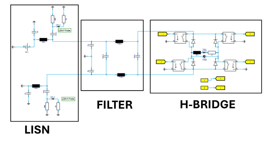
Goal: Build the H-Bridge + EMI filter as a circuit in CST (no PCB yet), excite it with PWM, and measure conducted emissions at the LISN port per CISPR 25 (V-method).

  • Create a Circuit project in CST Studio Suite.
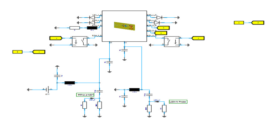
  • Refer to Fig. for the complete schematic: LISN → Filter → H-Bridge → Motor.

2. Excitations (PWM & supply)

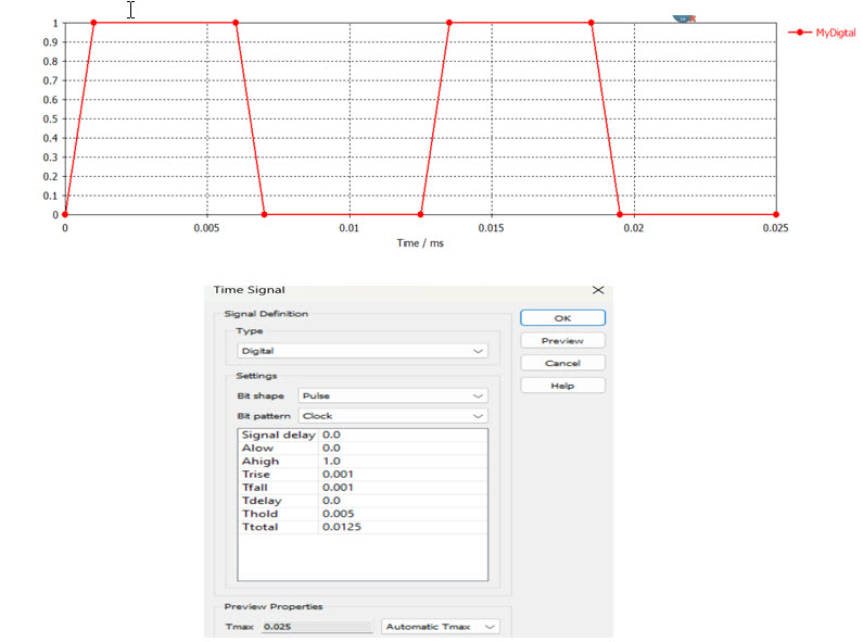
The PWM gate signals were generated using Digital → Pulse (Clock pattern) with logic levels 0/1. A rise/fall of 0.001 ms and ON-time of 0.005 ms within a 0.0125 ms period gives an 80 kHz PWM at ~40% duty cycle (≈ 5 µs high, 7.5 µs low). These signals drive the H-bridge Voltage-Controlled Switches, while the motor is modelled by a simple R–L equivalent.

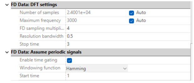
For reliable spectra, the transient simulation runs for 50–100 PWM cycles (≈ 0.6–1.2 ms). Frequency-domain analysis (up to 3 MHz) uses a 0.5 kHz RBW, Hamming window, and time gating from 1–3 ms to remove startup transients.

Fig: Excitation signal
Fig: FD data solver settings
3. CE Results and Observations
  • Without EMI Filter : Strong harmonics from PWM switching; several peaks exceed CISPR25 Class 1 → non-compliant.
  • With EMI Filter : Significant noise reduction; emissions stay below limits across all bands → compliant.

👉 Final takeaway: Filter is essential for passing CISPR25 in motor driver circuits.

  • X-axis → Frequency in kHz
  • Y-axis → Conducted emission level in dBµV (or dB, depending on CST setup)
Fig: CE Results of Motor controller with and without filters including CISPR25 CE Standard limits
4. PCB Design & Import into CST
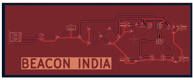
The designed schematic was captured in CST Circuit & System environment and later converted into a PCB layout using KiCad. The PCB was routed with proper net connections and exported in ODB++ format for CST import. This ensured that all nets, components, and layer stackup were preserved during transfer.
Fig: PCB design
5. Simulation Setup in CST
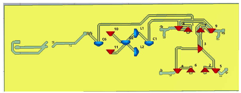
Inside CST, the imported PCB was connected according to the schematic. Excitations, loads, and measurement ports were assigned to replicate the circuit-level configuration. Special attention was given to ground return paths and supply rails to accurately reflect the conducted emission behavior.
Fig: Imported PCB
Fig: Schematic co-simulation connection.
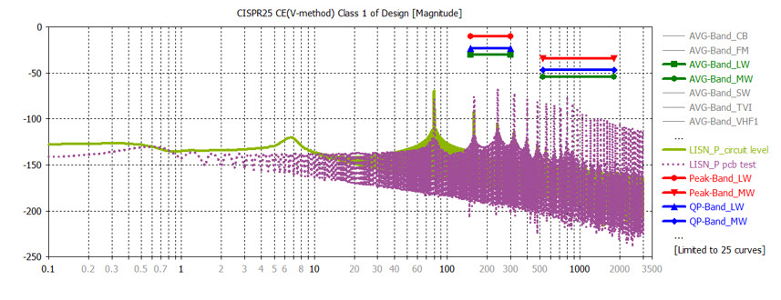
6. Simulation Results: Circuit vs PCB
  • Circuit-level (Green): Quick check with H-Bridge + LISN shows strong PWM harmonics but no PCB parasitic effects.
  • PCB-level (Purple): KiCad → CST ODB++ import shows cleaner spectrum; layout parasitics and grounding improve realism.
  • 👉 Conclusion: Green = early estimate, Purple = accurate validation. Both confirm PCB-level testing is essential for true CISPR25 compliance
  • X-axis → Frequency in kHz
  • Y-axis → Conducted emission level in dBV (or dB, depending on CST setup)
Fig: CE Results of Motor controller pcb level and Schematic level including CISPR25 CE Standard limits
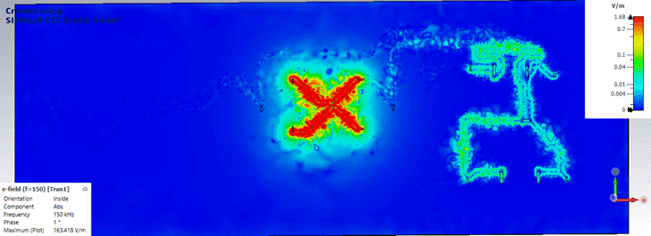
Fig: Emission Results of Motor controller  at 150KHZ.
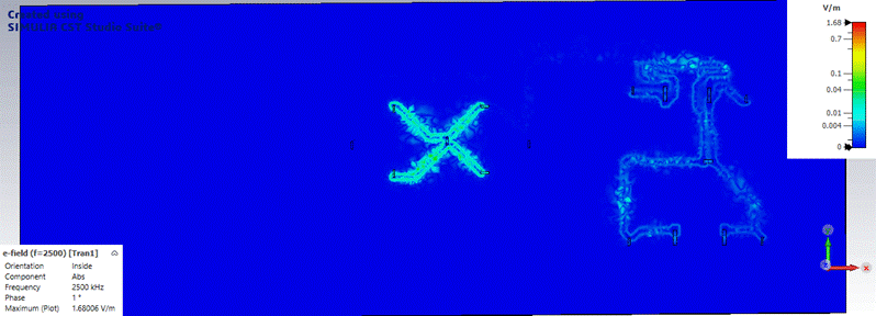
Fig: Emission Results of Motor controller  at 2500KHZ.
Conclusion

This study demonstrates a complete conducted emissions (CE) analysis workflow for an H-Bridge motor driver using CST Studio Suite. Starting from circuit-level modelling in CST Circuit & System, the design was progressively validated through LISN integration, EMI filtering, and transient analysis.

The schematic-only simulations provided an initial view of conducted noise generated by PWM switching. However, when the design was transferred into a PCB layout and simulated with parasitic effects included, the results showed noticeable differences. This highlights the importance of performing both circuit and PCB-level validation to obtain realistic EMI behaviour.

The LISN-based CE(V-method) measurements confirmed the impact of layout and filtering on emission levels. The filter stage played a crucial role in suppressing harmonic peaks and stabilizing the spectrum across the CISPR25-defined frequency bands. The comparison between schematic and PCB results underlines that early circuit simulations are valuable for rapid iterations, but PCB-level verification is essential for compliance assurance.

Overall, the workflow proves that CST Studio Suite enables a seamless transition from schematic design to full PCB validation, ensuring that emission performance can be predicted and optimized before hardware fabrication. This simulation-driven approach reduces prototyping costs, accelerates design cycles, and provides confidence in achieving regulatory compliance for automotive and industrial motor control applications.

Author

Guest Post by Mr. VENKATESH S S, Application Engineer, BEACON

To know more details, please reach out to us at:

Phone: +91 7406663589

Email ID: info@beacon-india.com Website: http://beacon-india.com

EMUGE-FRANKEN Introduces EvoGrip Modular Workholding System for 5-Axis Machining

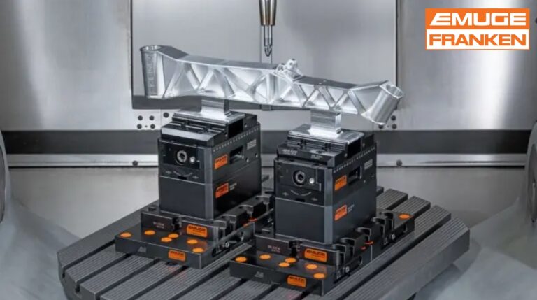
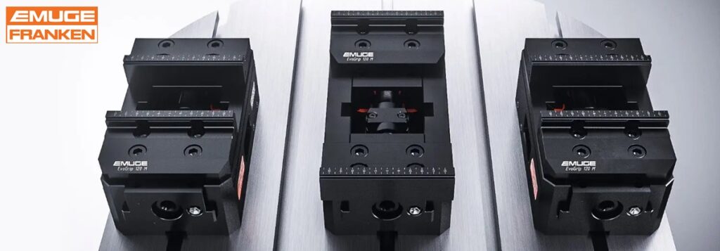
WEST BOYLSTON, MA, USA, Sep 9, 2025 – EMUGE-FRANKEN USA, a leading manufacturer of high-performance taps, thread mills, end mills, drills, gages, other rotary tools, and precision clamping solutions has introduced new EMUGE EvoGrip, a uniquely designed breakthrough modular workholding solution which includes its first standard high performance centering vise system. Designed to deliver maximum clamping force and full 5-Axis access in a compact solution setup, EvoGrip is ideal for aggressive milling operations. Three basic vise widths include 70 mm, 100 mm, and 120mm, and EvoGrip offers 25kN, 50kN and an exceptionally high 75kN clamping force. Starting at the mid-size 100 mm wide vise which is capable of 50kN clamping forces, EvoGrip vises are unmatched in the industry.

“Until now, EMUGE has been known for its custom workholding solutions to clamp the most challenging applications,” said Mr. David Jones, Precision Workholding Product Manager, EMUGE-FRANKEN USA. “We are very pleased to now offer our customers the rigidity and precision they expect from EMUGE in a standard, consistent workholding system with tremendous clamping forces.”

EvoGrip Centering Vises are manually operated and engineered for precise centric clamping, creating an extreme holding force of up to 75 kN despite a slimmer design than comparable products, so pre-embossing is not necessary. The slim, modular design enables multi-sided machining and facilitates easy integration into machining setups. Interchangeable top jaws can be mounted to the base jaw for use with different workpieces and machining requirements. Highly robust and stable guideways for the base jaws are precisely machined with EMUGE’s own end mills. Also, an integrated interface for automation provides two holding bores on either side of the basic vise body for machine gripper interfacing. This affords quick robot-controlled changeovers to the next workpiece, or even a totally different workpiece altogether.   

When EvoGrip Centering Vises are combined with the EMUGE EvoPoint Zero-Point Clamping System, setup times can be reduced by up to 80% versus when having to bolt down a clamping system. The modular EvoGrip System is scalable so that vises and zero-point interfaces can be configured to fit any machine tool or job. An integrated, robust EvoPoint zero-point clamping system provides automatic alignment using geometry similar to a pull stud, enabling fast, precise and repeatable clamping in the micron range, and the referencing of devices and workpieces on machine tools, machining centers and CMM’s. Repeatable accuracy of 0.005 mm and concentricity of ±0.02 mm is achievable with the EvoPoint System. The combination of EvoGrip with EvoPoint enables fast changeovers, high positioning accuracy, and exceptional holding force.

In addition, the reliable, repeatable EMUGE EvoGrip Workholding System includes EvoBlock solutions for machine table connections and riser options ranging from base plates to one-piece spacers. For customizing a solution to accommodate workpiece height requirements, machinable VarioBlock multi-piece spacers are available.

For more information on the new EvoGrip Modular Workholding Solution, click here.

About EMUGE-FRANKEN USA

EMUGE-FRANKEN USA is a wholly-owned subsidiary of the 1,950 employee German company EMUGE-Werk Richard Glimpel GmbH & Co. KG (Lauf, Germany). EMUGE-FRANKEN USA offers end-user technical support through a network of in-the-field engineers and in-house product specialists, all with extensive tooling and application experience. Over 10,000 types of cutting tools and accessories are stocked in the company’s U.S. and Canadian Headquarters located in West Boylston, MA, U.S.A. The recently expanded 50,000+ sq. ft. facility includes a technology center with a machining and tooling demonstration showroom and classroom, tool manufacturing and coating, reconditioning, warehouse, sales, support, and administrative offices. For more information on EMUGE-FRANKEN USA, call 800-323-3013, at 1800 Century Drive, West Boylston, MA 01583-2121, or visit www.emuge-franken-group.com.

About EMUGE-FRANKEN

For over 100 years, the German company group EMUGE-FRANKEN has been one of the world’s leading manufacturers of precision tools for thread cutting, drilling, gaging, clamping, and milling. With 1,950 employees, EMUGE-FRANKEN offers an innovative product program with 40,000 in-stock items and a multiple of that with customer-specific tools. The product range focuses on applications in the automotive industry, power plants, aerospace industry and medical technology as well as general manufacturing. As a complete system supplier for the machining industry, EMUGE-FRANKEN has branch offices or sales partners in 52 countries. 

Zuken Joins JOINT3 Consortium to Develop Next-Gen Semiconductor Packaging

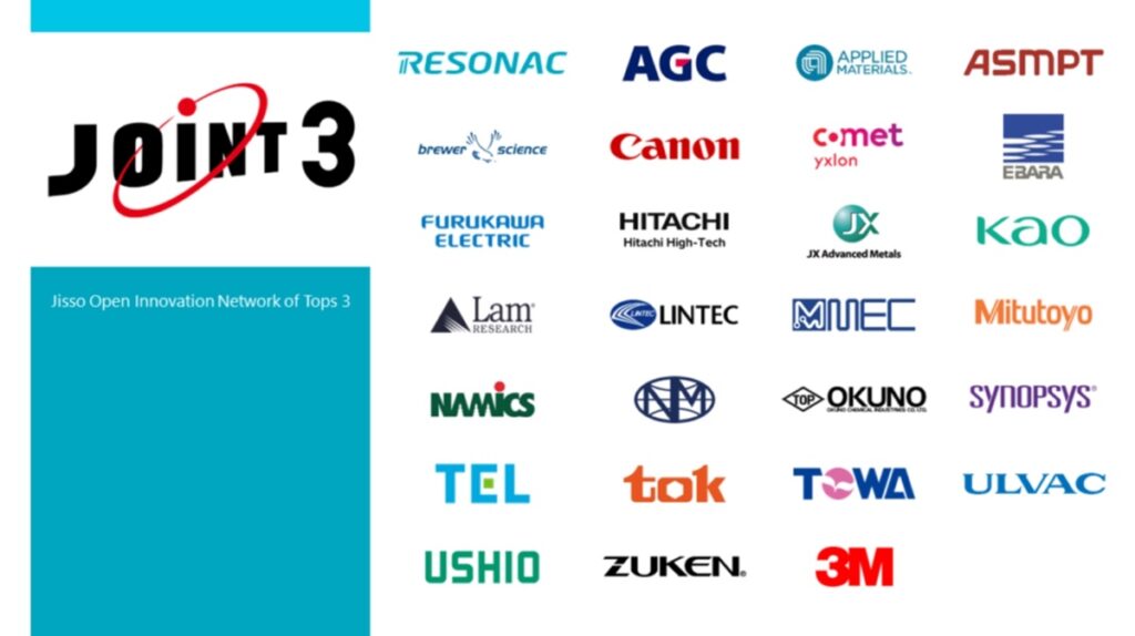
Zuken Inc. has joined “JOINT3” consortium to develop next-generation semiconductor packaging. JOINT3 is a co-creation evaluation framework established by Resonac Corporation (President and CEO: Hidehito Takahashi, hereinafter “Resonac”) with the aim of accelerating the development of materials, equipment, and design tools optimized for panel-level organic interposers through collaboration among material, equipment, and design companies. JOINT3 brings together global leaders in semiconductor supply chain. Using a prototype line for 515 x 510mm panel-level organic interposers, the consortium promotes the development of materials, equipment, and design tools optimized for panel-level organic interposers.

Based on Zuken’s track record and expertise as an EDA vendor supporting customers in advanced packaging design, we participate in the practical implementation of next-generation semiconductor packaging design, manufacturing, and verification with panel-level organic interposers in JOINT3. And Zuken contributes to the establishment of optimal design and manufacturing process by developing tools and features to solve issues that emerge in the process.

In recent years, packaging for back-end processes has emerged as a key technology in the field of next-generation semiconductors. This includes 2.xD packages, whereby multiple semiconductor chips are arranged in parallel and connected via interposers, demand for which is expected to grow in line with the need for increased data communication capacity and speed. As semiconductor performance improves, interposers are becoming larger, and there is a shift from silicon interposers to organic interposers made from organic materials.

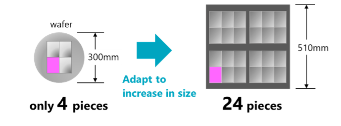
Conventional manufacturing methods involve cutting rectangular pieces from circular wafers. However, as interposers increase in size, the number of them that can be obtained from a single wafer decreases, posing a significant challenge. To address this issue, a manufacturing process that transitions from circular wafer shapes to square panel shapes is gaining attention, as it allows for an increased number of interposers to be produced from a given area of wafer.

Zuken has participated in various 2.5D and 3D package design, manufacturing, and verification projects, in addition to providing customers with advanced package design environments. Throughout the course of these projects, we have a proven track record in supporting the design and tool development for various technologies such as Chip stacking, Organic Package stacking, and various interposers. These experiences and technologies are consolidated into the CR-8000 Design Force’s 2.5DIC/3DIC design and verification features, and the SoC/package/PCB collaboration design environment.

In JOINT3, Zuken engages in the practical implementation and validation of next-generation semiconductor packaging design and manufacturing using panel-level organic interposers. In addition to verifying the physical structure design and electronics design, Zuken is also planning to develop new functions such as preliminary verification in the design stage that takes into account the physical properties and chemical characteristics of various materials.

By collaboration and co-creation with other JOINT3 members, Zuken contributes to the evolution of design, manufacturing, and verification process for the next-generation semiconductor packaging with panel-level organic interposers. And Zuken aims to play a key role in the next-generation ecosystem and supply chain.

About Zuken

Zuken is a global software company delivering advanced electrical and electronic design solutions. Founded in 1976, the company has built a strong reputation for technology innovation and financial stability in the EDA industry. Its flagship product families—CR-8000 for electronic design and E3.series for electrical systems—offer comprehensive 2D/3D system-level toolsets, backed by robust design data and configuration management capabilities. With its strategic entry into Model-Based Systems Engineering (MBSE), Zuken has embraced digital transformation, integrating MBSE tools and services with its established design platforms to meet the complex development needs of industries worldwide. For more information about the company and its products, visit www.zuken.com,  www.zuken.com/blog, or www.linkedin.com/company/zuken

Aras Announces 2025 Connect Europe Tour 

0

ANDOVER, MA, USA, Sep 9, 2025 – Aras, a leader in product lifecycle management (PLM) and digital thread solutions, announced the return of its Aras Connect Tour across Europe. The 2025 tour will make stops in four main cities, including Birmingham, Paris, Frankfurt, and Stockholm. The events will bring together business leaders, technology pioneers, and forward-thinking enterprises under the theme Connected Intelligence: AI, PLM, and the Future of Connectivity.

This event series is designed to showcase how the convergence of artificial intelligence (AI), PLM, and the digital thread is redefining agility, efficiency, and resilience in today’s dynamic business environment. Aras Connect 2025 will provide attendees with deep dives into the company’s latest platform advancements, customer success stories, and cutting-edge strategies to future-proof product development and operations. 

Each event will feature a dedicated Tech Summit for Aras builders – including engineers, software architects, and technical experts – offering in-depth technical tracks, live demos, and hands-on sessions with Aras product leaders. 

The events will take place on the following dates: 

Connect UK 

Connect France 

  • October 7-8, 2025 
  • Presenters include: CERN, Legrand 

Connect Germany 

  • October 14-15, 2025 
  • Presenters include: Grammer, Nicomatic 

Connect Nordics 

  • November 4-5, 2025 
  • Presenters include: Aeronamic, Legrand 

“As AI becomes a bigger part of how products are developed and supported, the need for connected, flexible solutions continues to grow,” said Leon Lauritsen, General Manager, Europe “At Aras Connect 2025, we’re bringing people together to talk about how to connect people, processes, and data across the digital thread – and what it really takes to make that work.” 

Whether you’re evolving your digital strategy or diving into the technical side of connected systems, Aras Connect 2025 delivers fresh perspectives and practical takeaways for organizations ready to lead in a connected future. 

Check out the Aras Conect event site to register or explore the agenda for each location. 

About Aras

Aras is a leading provider of product lifecycle management and digital thread solutions. Aras’ technology enables the rapid deployment of flexible solutions based on a powerful digital thread backbone and low-code development platform. Aras’ platform and product lifecycle management applications connect users of all disciplines and functions to critical product data and processes across the entire lifecycle and extended supply chain. Visit www.aras.com to learn more and follow us on YouTubeXFacebook, and LinkedIn.

Kawasaki Robotics Launches neoROSET Visual Inspection Tool VI Planner

0

WIXOM, MI, USA, Sep 9, 2025 – Kawasaki Heavy Industries Robot Business Division has launched the “neoROSET VI Planner” (VI: Visual Inspection), a tool equipped with teaching and simulation functions for visual inspection robots.

neoROSET VI Planner is an extended plugin of the robot simulation software “neoROSET,” released at the end of last year. It includes three applications tailored for inspecting products with complex shapes: “Path Creator,” “SLiM,” and “Path Editor.” These applications enable automated surface-normal teaching (Path Creator), visualization of inspection coverage through lighting simulation (SLiM), and automatic generation of robot motion programs (Path Editor), significantly improving teaching accuracy and operational efficiency.

Compared to conventional manual teaching, the average teaching time per product type can be reduced by approximately 16 hours. This contributes to shortening and advancing production preparation periods, reducing line downtime, and minimizing labor costs such as weekend work.

For more information about neoROSET VI Planner, visit https://kawasakirobotics.com/in/products-others/neoroset.

About Kawasaki Robotics

With over 50 years of experience in the automation industry, Kawasaki is a leading supplier of industrial robots and robotic automation systems with expertise in a wide range of applications and industries. Delivering the best value robot offerings by providing a rich set of standard features on all robot models for application flexibility, renowned Kawasaki quality and performance, and unmatched customer support and after sales service. Learn more about Kawasaki Robotics here, watch robot application videos here and connect on Twitter, Facebook and LinkedIn.

Xometry Publishes 2026 Manufacturing Outlook Report

NORTH BETHESDA, MD, USA, Sep 9, 2025 – Xometry, Inc. (NASDAQ:XMTR), the global AI-powered marketplace connecting buyers with suppliers of manufacturing services, unveiled its inaugural Manufacturing Outlook report, a forward-looking analysis of the forces shaping the manufacturing industry for 2026.

Drawing on proprietary research with manufacturing executives across the U.S., U.K. and Europe, along with insights from Xometry and external subject matter experts, the Manufacturing Outlook provides a global perspective on strategies and capabilities that will define success in the year ahead. It is designed as a resource for decision-makers across the manufacturing industry, offering practical insights to help them navigate rising expectations, accelerating technology, and persistent cost pressures.

The report identifies four trends that will shape global manufacturing in 2026:

  1. AI as a Competitive Necessity – 82% of executives view AI as a core growth driver, with nearly half already reporting significant ROI. AI has moved beyond the hype to become a business-critical tool for manufacturing, and adoption is expanding into critical areas such as supply chain, procurement and quality control—areas that will set the pace for industry innovation.
  2. Agility as the New Currency – 74% of executives are reshoring or planning to restore operations, underscoring the need for resilient digital workflows. The most successful companies will be those that proactively architect systems for speed, resilience and adaptability. Integrating digital workflows and strengthening supplier networks will help manufacturers reduce overhead, move faster and empower teams to focus on high-value tasks.
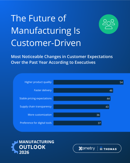
  3. Rising Customer Expectations – 54% of executives cite higher quality demands, with faster delivery and greater transparency also among the most striking shifts in customer demands. In response, manufacturers are embracing market-driven pricing strategies and forming strategic partnerships that extend beyond traditional cost, quality and speed considerations.
  4. Sourcing for Stability – With 76% planning price increases in 2026, manufacturers are rethinking their pricing models and supply chains to stay competitive. In response, there is a notable shift toward market-driven pricing emerging. Instead of rigid formulas, many companies are embracing new strategies including forming strategic partnerships and diversifying suppliers across regions.

“Manufacturers are under intense pressure to do more with less and to meet growing customer expectations, even as costs are rising and global disruptions persist,” said Randy Altschuler, CEO at Xometry. “This report reflects the conversations we’re having every day with manufacturers about the challenges and opportunities ahead. The Manufacturing Outlook is intended to serve as a barometer for where the industry is headed and how companies can prepare.”

Download the Report

The 2026 Manufacturing Outlook is available now, with insights tailored for the United States and European markets.

Methodology

All data points are sourced from Xometry, Thomas, and a joint survey conducted by Xometry and Zogby Strategies. The survey was conducted in August 2025 and had a total of 300 respondents.

About Xometry

Xometry’s (NASDAQ: XMTR) AI-powered marketplace, popular Thomasnet industrial sourcing platform and suite of cloud-based services are rapidly digitizing the manufacturing industry. Xometry provides manufacturers the critical resources they need to grow their business and streamlines the procurement process for buyers through real-time pricing and lead time data. Learn more at xometry.com and xometry.eu.