

GUEST POST BY Mr. Nikhil M, Application Engineer – Simulation, BEACON India
1. Introduction to Pressure Vessels and SOLIDWORKS Simulation
Pressure vessels are vital in industries like oil and gas, storing fluids under pressure. Safety is paramount, guided by standards like ASME BPVC. SOLIDWORKS Simulation’s Pressure Vessel Design Module helps analyze stress and deformation, ensuring compliance. Key to this is stress linearization, separating stresses into components to verify they meet allowable limits. This module streamlines the process, enhancing safety and reliability.
2. Problem Definition
Leading pressure vessel manufacturer needs to assess a high-pressure steam drum for a cogeneration plant. Operating at 2 MPA and 75°C, the drum, made of SA-516 Grade 70 steel, will experience pressure, gravity, and thermal stresses. The goal is to ensure safety and reliability while complying with ASME BPVC.
3. Simulation setup
Boundary Conditions and External Load Fixtures:
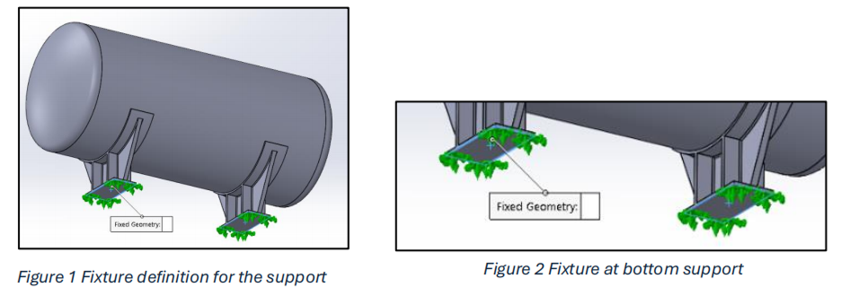
A fixed constraint is applied to the faces at the bottom of both support plates, preventing any displacement or rotation in those directions.
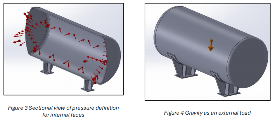
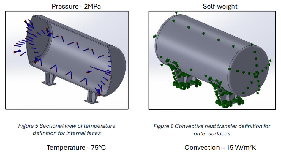
External load:
A pressure load of 2 MPA (20 bar) is applied to the vessel’s internal surfaces. Additionally, a thermal load representing a 75°C temperature rise is applied internally with convection coefficient of 15 W/m2K. Finally, the weight of the vessel is considered by applying a gravity load. These loads are then superimposed and analyzed within the Pressure Vessel module to assess the combined stress state.
Pressure Vessel Details:
- Material: SA-516 Grade 70 (Carbon Steel)
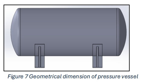
- Dimensions:
- Length: 3 m
- Outer Diameter: 1.5 m.
- Wall Thickness: 20 mm
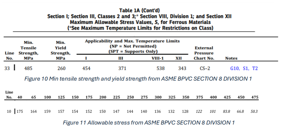
ASME Boiler and Pressure Vessel Code, Section VIII, Division 1 for Torispherical Head design.
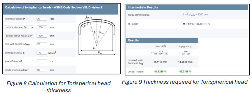
Refer the site calculation for Torispherical head thickness:
https://www.cis-inspector.com/asme-code-calculation-kloepperboden.html
Required Wall Thickness (treq):
- Calculated using two different equations from the ASME Code
- Equation I: treq = (P * L * M) / (2 * S * E + P * (M – 0.2)) = 14.1115 mm
- Equation II: treq = (P * L * M) / (2 * S * E) = 14.0515 mm
- The required wall thickness is typically taken as the higher value from these two equations, which in this case is 14.1115 mm
This calculation determines the minimum required wall thickness for a torispherical pressure vessel head to safely withstand the specified internal pressure according to the ASME Code. The results show that the initial estimated wall thickness of 20 mm is significantly higher than the required thickness, indicating a substantial design margin.
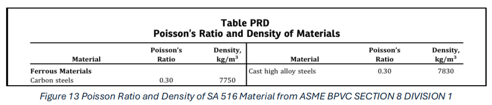
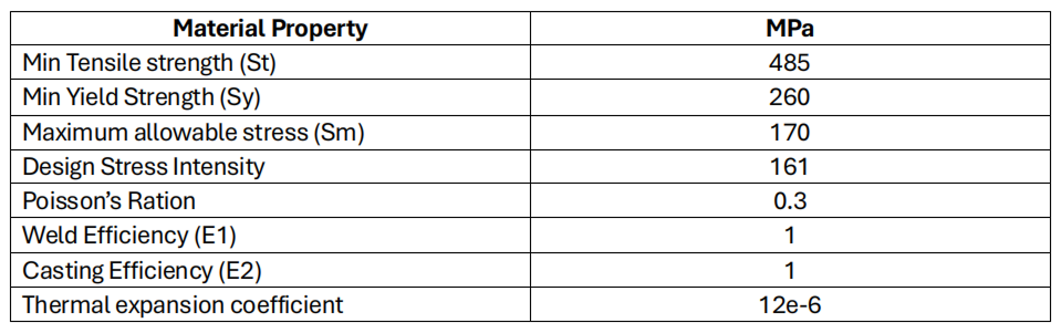
4.Material property (ASME BPVC Code SECTION VIII DIVISION I &II)
SA-516 Grade 70
SA-516 is a high-strength, low-alloy steel renowned for its suitability in demanding pressure vessel applications, particularly those operating at elevated temperatures. This material excels due to its impressive combination of strength, toughness, and resistance to creep and fatigue.
Key Advantages of Using SA-516:
SA-516 offers high strength, excellent weldability, and maintains integrity at elevated temperatures. This industry-standard material enables cost-effective, reliable pressure vessel designs that meet ASME BPVC requirements.
By selecting SA-516 for our analysis, we can accurately model the vessel’s behavior under operating conditions, ensuring the design meets the highest safety and performance standards. Material properties for SA-516 were determined based on the relevant ASME BPVC code provisions for the specified operating temperature of 75°C.
5.Stress Categorization and Code Compliance (ASME Section VIII, Division 2):
Imagine a pressure vessel as a sturdy container holding fluids or gases under pressure. The forces within and around this vessel create different types of stress that engineers must carefully analyze.
- General Membrane Stress is like the vessel’s steady heartbeat – a uniform stress spread evenly across the wall thickness. It’s the primary concern for overall vessel integrity and must stay within strict limits defined by codes like ASME. Excessive general membrane stress can lead to deformation or even rupture.
- Local Membrane Stress occurs at points of disturbance like nozzles or junctions. Think of it as a localized increase in pressure. While it can cause yielding in specific areas, it’s generally less critical than general membrane stress as long as the affected area is limited.
- Bending Stress is like the vessel flexing. It arises from external loads, uneven pressure, or sudden changes in shape, causing one side of the wall to experience tension while the other experiences compression. Bending stress is significant at supports, reinforcements, and transitions. If combined with high membrane stress, it can lead to deformation and even buckling.
Understanding these stress types is crucial for ensuring the safety and reliability of pressure vessels.
Stress Categories (Per ASME Code):
Terminologies
- Sm (basic allowable)
- Sya (yield strength at ambient temp.)
- Sta (tensile strength at ambient temp.)
- E (modulus of elasticity)
- E1 (weld efficiency)
- E2 (casting efficiency)
- v (Poisson’s ratio) -Table PRD
- Coeff (coefficient of thermal expansion)Stress Limit Equations: VIII-2
- Pm = E1*E2*Sm – general primary membrane stress limit (material only)
- Pl = 1.5*E1*E2*Sm – local membrane stress limit
- Pl+Pb = 1.5*E1*E2*Sm – primary membrane + primary bending stress limit (material only)
- Pl+Pb+Q = Max(3*E1*E2*Sm,2*E1*E2*Sy) – primary + secondary stress (2*Sy only valid for Sya/Sta <= 0.7)
Comments:
- Sy material property is not required, more conservative Pl+Pb+Q limits might be computed without it.
- The thermal expansion coefficient is only required for studies including thermal stresses
- Refer to VIII-2 5.15 Figure 5.1 and following for the Pm, Pl, Q and F stress
- Refer to VIII-2 5.14 Table 5.6 for the correct application of the calculated stress limits
- Use IID tables 5A and 5B for Sm for VIII-2 studies
- Use IID tables 1A and 1B for Sm values (S) for VIII-1 studies
- Use B31.1 Table A-1, A-2, A-3 for Sm values for B31.1 studies
- Use B31.3 Table A-1 for Sm values for B31.3 studies
- 2*Sy Pl+Pb+Q not valid when in creep range
FOR FURTHER DETAILS Check – READ MORE ON BEACON India website

")