Home Blog Page 772

ALLPLAN Updates Bimplus, Features Enhanced Project Collaboration, Clash Detection, Model Access Control

0

MUNICH, Germany, May 19, 2020 – ALLPLAN, the global provider of open solutions for Building Information Modeling (BIM), presents the latest release of Allplan Bimplus with several improvements and new features. Bimplus is tailor-made for architects, engineers, fabricators, project managers, clients and whole project teams who require a data-driven, cloud-based collaboration environment. This openBIM collaboration platform underpins the BIM process, enabling efficiencies across the entire project lifecycle – from design to delivery, and even maintenance and operation.


Project Navigation with Allplan Bimplus


Construction projects are often delivered late, over budget, and to inadequate quality standards, usually as a result of ineffective communication, planning, and collaboration. In order to overcome these challenges, the construction industry must find ways of working that allow them to deliver safe, fit-for-purpose projects faster and with fewer resources. The reasons for these inefficiencies are broadly common across the industry. According to a survey sponsored by ALLPLAN, incomplete data from different disciplines, design changes, and problematic information exchange are highlighted as sources of poor communication. Without clear and transparent communication between all parties, the benefits of meticulous planning and collaboration cannot be realized.

“For many years BIM has been used to improve communication and collaboration, providing a method of coordinating works for improved overall project delivery. BIM helps avoid rework by identifying clashes earlier between components and allows material usage to be optimized and waste reduced. In turn, these advantages help deliver projects quicker and more efficiently. As integrated project information, effective communication, and efficient design have become synonymous with BIM, it has become increasingly demanded by clients worldwide. Bimplus helps maximize the benefits of BIM, ensuring that any BIM implementation is successful”, says Kevin Lea, Senior Vice President Product Management, ALLPLAN.

Feature-Rich Support for BIM

Bimplus helps address concerns with project management, information management, change management, coordination, and collaboration, ensuring that any BIM implementation is successful. The latest release of Bimplus includes several improvements to existing features, including clash detection with custom filters, model access control with rights and roles and user management with groups. BIM workflows to ISO19650 include model discipline validity and IFC export of selected model topologies is supported, together with a customizable building topology manager. Furthermore, packaging and associated pricing has also been updated to improve customer choice, deliver optimal value and reflect the collaborative nature of the usage of Bimplus across projects large and small.


Clash Detection with Allplan Bimplus


Highlights of Allplan Bimplus:

Improved Project Management

Bimplus helps ensure that projects are organized logically, so information is easily accessible to anyone who needs it. Access rights and roles can be quickly and easily assigned so the right people can edit the right information, without affecting the transparency of the project.

Better Information Management

Digital projects quickly create large amounts of information that require organizing and managing in order to add value. With Bimplus, information from multiple sources and in multiple formats can be easily stored, accessed, and managed with complete document management features. Revisions of both documents and models are stored within the platform for ease of access, and information can be accessed via Bimplus from any device that has an internet connection.

Enhanced Change Management

Scope changes quickly erode design and construction budgets. With Bimplus, any changes can be visualized and compared before being confirmed, enabling informed decisions to be made earlier in the process. In turn, this reduces the risk of errors and discrepancies within the project and mitigates the impact of any changes.

Superior Coordination

Projects are rarely designed by one team or discipline in isolation. Coordinating these different inputs is essential in order to avoid errors and increased costs. Bimplus employs an approval process workflow for sharing models based on the international ISO19650 standard, so even global teams are working to the same standard of information management. The database structure used by Bimplus allows the platform to do more with the information, such as combine and visualize models, assign attributes and object information, and run clash detection checks or simulations.

Increased Collaboration

Collaboration between the project team should not be restricted to one software manufacturer’s format. Bimplus uses the principles of openBIM, including the industry standard IFC data exchange format, to import and export models. This allows information to be read by all the project participants irrespective of the file format used, and ensures no information is lost due to file incompatibility.

Availability

The latest release of Allplan Bimplus is available to download for a free trial now: WWW.BIMPLUS.NET

About ALLPLAN

ALLPLAN is a global developer of open solutions for Building Information Modeling (BIM). For more than 50 years ALLPLAN has pioneered the digitalization of the construction industry. Always focused on the clients we provide innovative tools to design, construct and manage projects – inspiring users to realize their visions. ALLPLAN solutions are being used by over 240,000 architects, engineers, contractors and facilities managers in 20 languages. Headquartered in Munich, Germany, ALLPLAN is part of the Nemetschek Group. Around the world, over 400 dedicated employees continue to write the ALLPLAN success story. For more information, visit www.allplan.com.
Invitation
Siemens sd17

MakerBot Launches METHOD Carbon Fiber 3D Printer

0

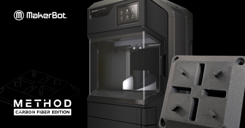
BROOKLYN, NY, USA, May 19, 2020 – MakerBot, a global leader in 3D printing and subsidiary of Stratasys (Nasdaq: SSYS), moves into the next level of 3D printing with the launch of the METHOD Carbon Fiber Editions. The new METHOD Carbon Fiber Editions are designed to enable engineers to print stronger and more accurate parts for manufacturing tools, jigs and fixtures, and end-use production, and can be used to print metal replacement parts in some applications.


MakerBot METHOD Carbon Fiber Edition (Photo: Business Wire)
MakerBot METHOD Carbon Fiber Edition


The latest additions to the METHOD platform, the METHOD Carbon Fiber Editions print carbon fiber reinforced nylon that is optimized for high strength and heat resistance. The new METHOD and METHOD X Carbon Fiber Editions come pre-configured with a new composite extruder that is optimized to handle abrasive materials. The new extruder, which is also available as an upgrade for the METHOD and METHOD X 3D printers, has hardened metal drive gears, a metal filament switch, and an interchangeable hardened steel nozzle. It can print MakerBot Nylon Carbon Fiber material and all other model materials supported on the METHOD platform.

The new MakerBot Nylon Carbon Fiber material is an ideal lightweight alternative to metal for structural applications such as vehicular brackets and inspection gauges, manufacturing tools such as robotic end effectors, and under-hood applications. Due to its strong thermal and mechanical properties, carbon fiber is frequently used in manufacturing, automotive, and aerospace industries. Used as an alternative to metal parts, carbon fiber can help reduce costs and increase overall efficiencies for companies.

“Nylon carbon fiber is one of the most in-demand and exciting classes of materials. Its high strength, heat resistance, and stiffness properties make it ideal for printing metal replacement parts, helping reduce costs and increase overall efficiency for companies,” said Nadav Goshen, President and CEO, MakerBot. “With the launch of METHOD Carbon Fiber, we are making composite 3D printing more accessible to more users than ever before and opening the door to new applications. METHOD Carbon Fiber is the latest addition to the rapidly growing METHOD 3D printing platform.”

METHOD’s heated chamber produces strong manufacturing-grade nylon carbon fiber parts with superior surface finish. Users can print complex geometries with internal cavities using MakerBot’s PVA soluble support material and anneal the final part for extra strength with METHOD’s new heated chamber annealing feature. With the METHOD X Carbon Fiber Edition, users can print complex geometries using Stratasys® SR-30™ soluble supports for an even better surface finish. Breakaway supports are also available for faster print results. METHOD’s dry-sealed filament bays help to keep the moisture-sensitive nylon carbon fiber material dry, resulting in better print quality and reliability.

MakerBot plans to offer additional composite materials available for the METHOD Carbon Fiber Editions and the composite extruder for METHOD in the future. Since the METHOD X has a higher chamber temperature than METHOD of up to 110°C on the build plane, it will be able to support a wider range of high-performance composite materials in the future.

The METHOD platform features industrial 3D printing capabilities that make it ideal for printing with advanced, engineering-grade materials. The combination of a heated chamber, ultra-rigid steel frame, sealed material bays, performance extruders, and dissolvable supports enable engineers to print consistently accurate parts. METHOD offers a diverse portfolio of materials for a variety of engineering applications. MakerBot materials include Nylon Carbon Fiber, PC-ABS, PC-ABS FR, ABS, ASA, Nylon, PETG, Tough, PLA, and support materials SR-30 and PVA. Additionally, with the availability of the MakerBot LABS extruder for METHOD, users can print with more industrial materials from leading material suppliers.

For more information, visit www.makerbot.com/carbon.

Availability

The METHOD Carbon Fiber Editions, MakerBot Nylon Carbon Fiber material, and the composite extruder are expected to begin shipping in June 2020.

About MakerBot

MakerBot, a subsidiary of Stratasys Ltd. (Nasdaq: SSYS), is a global leader in the 3D printing industry. The company helps create the innovators of today and the businesses and learning institutions of the future. Founded in 2009 in Brooklyn, NY, MakerBot strives to redefine the standards for 3D printing for reliability, accessibility, precision, and ease-of-use. Through this dedication, MakerBot has one of the largest install bases in the industry and also runs Thingiverse, the largest 3D printing community in the world.

We believe there’s an innovator in everyone, so we make the 3D printing tools that make your ideas matter. Discover innovation with MakerBot 3D printing.

To learn more about MakerBot, visit makerbot.com, the MakerBot blogTwitterLinkedIn, or Facebook. Stratasys (the parent company of MakerBot) reserves the right to utilize any of the foregoing social media platforms, including the company’s websites, to share material, non-public information pursuant to the SEC’s Regulation FD. To the extent necessary and mandated by applicable law, Stratasys will also include such information in its public disclosure filings.

Zuken Releases Harness Builder 2020 for E3.series

0

WESTFORD, MA, USA, May 19, 2020 – Zuken’s Harness Builder 2020 for E3.series has been enhanced to provide extended control and processing capabilities for wire harness manufacturers. Harness Builder for E3.series is a packaged solution that allows harness manufacturers to generate accurate customer quotations. From there, the underlying design database can be reused–not reinvented–to create the manufacturable formboard design, saving time, and maintaining the accuracy of the design.

“We’re edging closer to the perfect solution for creating wire harness quotations faster and more accurately while providing the functionality to enter the manufacturing stage much earlier by using the same tool for both jobs”, comments Paul Harvell, Product Director of E3.series.

Auto-placement of device and cable labels

The Auto-placement of device and cable labels, along with heat shrinks, substantially decreases the tedious job of manual measurement and placement on the harness drawing. Labels are dynamically selected based on wire bundle size and auto-placed on connector ends or on the complete harness. The label data becomes part of the system and can be printed locally or sent to industrial label printing machines during the harness assembly process.

User-definable content is extracted directly from the design for printing or exported to vital build documentation eliminating the need to check for compatibility and accuracy of the information against the design.

The new release features auto-placement of tape and/or fixings in predefined positions on nets and set distances from the connector ends. Tape, labels, and heat shrinks are automatically added to the quotation and the bills of materials if required.


HB202020automatic20label20placementAutomatic label placement menu


Drafting co-pilot

Harness Builder 2020 for E3.series includes a new drafting co-pilot that allows the user to enter predefined wire or cable lengths. Now a fixed-length cable can be wound around a pin or peg on the formboard, maintaining the predefined length without requiring orthogonal placement. This means a much smaller formboard can be used for building the harness, occupying less space on the manufacturing floor.


HB202020Drafting20Co-pilotDrafting co-pilot to assist with the layout of long cable runs


Support for third-party test and manufacturing equipment

Support for third-party test and manufacturing exports has been expanded. Harnesses created with Harness Builder 2020 for E3.series can now be exported directly to CableScan for testing. This integration adds to our growing list of supported vendors that includes Cami Research, Cirris, DIT-MCO, and Dynalab.

Also included in the 2020 release is a new export utility to drive the ProjectionWorks (a division of Delta Sigma) family of manufacturing equipment. Harness placement and wiring information is exported from the Zuken tool and projected directly on the formboard as augmented reality work instructions. This combined solution reduces manual errors and speeds time to manufacture.

Cable tolerancing

Based on feedback from the military sector, Harness Builder 2020 for E3.series now employs a user-driven tolerancing panel, influencing cable lengths. When setting cable tolerancing, this new feature provides the user with a sliding scale of tolerance based on the length and complexity of the cables, improving the overall build accuracy.


HB202020wire20detailing-768x844nhanced wire detailing for accurate cable protection selection
 

Availability

Harness Builder 2020 for E3.series is available now in North America.

About Zuken

Zuken is a global provider of leading-edge software and consulting services for electrical and electronic design and manufacturing. Founded in 1976, Zuken has the longest track record of technological innovation and financial stability in the electronic design automation (EDA) software industry. The company’s extensive experience, technological expertise and agility, combine to create world-class software solutions. Zuken’s transparent working practices and integrity in all aspects of business produce long-lasting and successful customer partnerships that make Zuken a reliable long-term business partner. For more information, visit www.zuken.comblog.zuken.com, or www.linkedin.com/company/zuken.

Autodesk Construction Cloud Adds Assets Module, Allowing Teams to Track Project Assets Through Entire Building Lifecycle

0

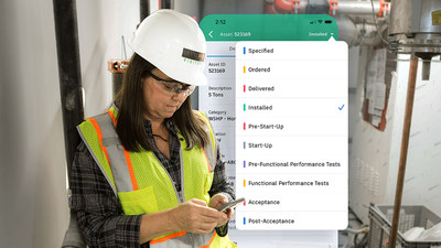
SAN RAFAEL, CA, USA, May 19, 2020 – Autodesk, Inc. (NASDAQ: ADSK) today announced the early release of the BIM 360 Assets module within Autodesk Construction Cloud. The BIM 360 Assets module enables construction teams to track and manage project assets through the entire building lifecycle – from design through handover – from one centralized location. The new module also gives construction teams increased access to asset data in the field, allowing them to perform commissioning and resolve defects on-site, decreasing the time to operations and ultimately reducing risk. The new BIM 360 Asset module will be included as part of BIM 360 Build subscriptions and generally available starting in mid-June.


BIM 360 Assets can easily track all construction assets such as materials (concrete, wood, drywall), components and equipment (air handling units, pumps, chillers, elevators), moveable equipment (forklift, excavator, concrete buckets) and rooms or areas.

“With the BIM 360 Assets module, we’ll be able to deliver a complete and fully linked archive of all construction assets, streamlining the handover process from construction to operations,” said Simon Terroitin, BIM coordinator at EBC, Inc. “BIM 360 Assets will allow us to better collaborate with our clients during site construction and give them exactly what they need right after construction completes. We see this having a significant impact on building client relationships and winning future business.”

“The world in which we live today underscores the importance of resiliency, including project and data continuity,” said Sameer Merchant, head of research and development for Autodesk Construction Solutions and associate vice president at Autodesk. “For project owners and contractors, this means spreadsheet-based asset tracking must evolve into a single source of truth for all assets, accessible by all teams at any time. BIM 360 Assets will improve both day-to-day workflow and handover, and subsequently become a part of any successful company’s future resiliency program. This is yet another way Autodesk Construction Cloud is helping construction teams efficiently manage the entire building lifecycle with data flowing from design through to operations.”

BIM 360 Assets connects asset data management for contractors and owners

Traditionally, assets have been tracked using multiple spreadsheets or paper-based tools, a disorganized and time-consuming process particularly when an asset needs to be accounted for throughout the lifecycle of a project. When asset data is disconnected from the project and in siloes, asset tracking – such as determining the installation status of an HVAC unit, pinpointing the location of an excavator or scheduling interior finishes that require a long lead time – can be inefficient. This lack of connectivity can lead to scheduling delays, cost overruns, and potential liability if assets are installed incorrectly – not to mention poor client satisfaction when the owner is obliged to assume responsibility during facility management set-up.

BIM 360 Assets provides a user-friendly and centralized location to track all construction assets from planning through to operations.

Key features of BIM 360 Assets include:

  1. Centralized documentation – Quickly access all asset information including product information such as cut-sheets, certifications, training materials and warranty documents through a centralized repository.
  2. Connect asset data from quantity take-off – Easily extract asset data directly from the model and import into BIM 360, allowing the office team to track assets in the field and with a bi-directional connection, see progress visualizations in Assemble.
  3. Integrated field management workflows – Connect assets and commissioning efforts to other field management workflows like documenting defects using Issues and completing inspections with Checklists – all from a mobile device.
  4. Barcode / QR code scanner – Carry out relevant inspections and ongoing maintenance effortlessly with the simple scan of a barcode or QR code from your mobile device.
  5. Importing and customization – Quickly populate an asset list from spreadsheets and then easily track when an asset has been specified all the way through acceptance using custom categories, statuses and attributes.

For contractors, BIM 360 Assets offers the ability to align project assets to the model, ensuring all teams have up-to-date information, and also provides a digital trail of what issues have been resolved during installation. These new capabilities also help minimize future risk and litigation by tying a historical record to each asset. For owners, data handover saves significant time and provides an in-depth understanding of changes made to the building as far back as during the design process. For example, an owner will be able to scan a piece of equipment, get a historical record of when it was installed and by whom, have immediate access to documentation and know when maintenance needs to be scheduled.

“At PARIC, we are focused on finding the best enterprise solutions and solving for hundreds of projects rather a single one,” said Andy Leek, vice president of technology & innovation at PARIC. “The new BIM 360 Assets module provides a cleaner way to manage equipment sets and other facility components across the entire company. We’ll be able to simplify project set-ups and in turn, decrease miscommunication to eliminate rework and reduce risk at handover.”

To learn more about the BIM 360 Assets module, visit the Autodesk Construction Cloud Assets webpage. Existing customers who are interested in taking advantage of early access to the BIM 360 Assets module can reach out directly to their customer success manager or sales representative. The new Assets module will be added to all BIM 360 Build account subscriptions when it is commercially available in mid-June, 2020.

About Autodesk

Autodesk makes software for people who make things. If you’ve ever driven a high-performance car, admired a towering skyscraper, used a smartphone, or watched a great film, chances are you’ve experienced what millions of Autodesk customers are doing with our software. Autodesk gives you the power to make anything. For more information visit https://www.autodesk.com or follow @autodesk.

Creaform Launches 3D Metrology Webinar Series for North America

0

LEVIS, QC, Canada, May 18, 2020 – Creaform, a worldwide leader in 3D measurement solutions and engineering services, is launching a new webinar series for North America. From non-destructive testing to quality control, the series will showcase Creaform’s technology solutions for a variety of industries and serve as an open forum to engage with Creaform’s experts.

From mid May to mid June, the Ask an Expert series will feature a new topic every Wednesday and include a brief demonstration followed by a question and answer session:

  1. ‘Fastest & Safest’ NDT Pipeline Inspection
    1. Wednesday, May 20, 1pm EDT
    2. Field crews are facing challenges to complete pipeline inspections and integrity assessments in the shortest time. Creaform’s solution, which includes a 3D scanner and Pipecheck software, saves both time and money without compromising diagnostic results, public safety and the integrity assessment.
  2. ‘Get it right the first time’ Product Design
    1. Wednesday, May 27, 1pm EDT
    2. Designing a product that needs to fit existing equipment, trucks, motorcycles, or other machinery?  Learn how 3D Scanning is the fastest and most effective way to get your designs right the first time.
  3. Aircraft Maintenance & Repair
    1. Wednesday, June 3, 1PM EDT
    2. Consumer travel may be down, but aircraft are still being used to deliver essential goods and services and military aircraft must always be ready.  Reduce your downtime with 3D scanning for dent analysis, part design and inspection reporting.
  4. Fixture Analysis, Adjustment & Traceability
    1. Wednesday, June 10, 1PM EDT
    2. Fixtures are the backbone of the manufacturing industry and need to remain within specification. Learn how portable 3D scanning can be used to increase accuracy, reduce downtime and save money.

In addition to making this new webinar series available free for everyone, Creaform has also increased virtual opportunities for current customers, including training and free software for at-home use. While expanding learning opportunities and maintaining operations, Creaform and its technologies continue to play a vital role in the international response to COVID-19. Read more>>

About Creaform

Creaform develops, manufactures, and sells 3D portable and automated measurement technologies and specializes in engineering services. The company offers innovative solutions for applications such as 3D scanning, reverse engineering, quality control, non-destructive testing, product development, and numerical simulation (FEA/CFD). Its products and services cater to a variety of industries, including automotive, aerospace, consumer products, heavy industries, healthcare, manufacturing, oil and gas, power generation, research and education.

With headquarters and manufacturing operations in Lévis, Québec, Creaform operates innovation centers in Lévis as well as Grenoble, France, with direct sales operations in 13 countries, including Germany, Japan and Mexico. Creaform is part of AMETEK Ultra Precision Technologies, a division of AMETEK Inc., which a leading global manufacturer of electronic instruments and electromechanical devices, with annual sales of approximately $5 billion. For more information, visit https://www.creaform3d.com. 

BETA CAE Systems Releases ANSA, EPILYSIS, META Suite v19.1.7

0

LUCERNE, Switzerland, May 18, 2020 – BETA CAE Systems announces the 7th bug-fix release of ANSA/EPILYSIS/META v19.1.x series. This version particularly hosts fixes in detected issues, but also a few noteworthy enhancements and implementations.


suite_19.1.7


Follows a selection of the most important items:

Enhancements and known issues resolved in Licence Management

A message dialog window pops up when a specific session requires more license credits than those available.

For more details about the new software features, enhancements and corrections please, refer to the Release Notes document.

Known issues resolved in ANSA

Translators

CATIA files designed in R29, would not be imported properly in ANSA, leading to missing Faces.

Connections & Assembly

Import of the VIP2 files in ANSA would lead to bad interpretation of VIP2 Subtype attribute.

Applying Template Scenario to connections performance issue fixed.

Plug-ins

Test/Impact Device Positioning Plugin would not run for NASTRAN or unsupported solvers.

For more details about the new software features, enhancements and corrections please, refer to the Release Notes document.

Known issues resolved in META

Automation

The command “window arrange convert” would not perform as expected.

For more details about the new software features, enhancements and corrections please, refer to the Release Notes document.

Compatibility and Supported Platforms

ANSA files saved by all the first and second point releases of a major version are compatible to each other. New major versions can read files saved by previous ones but not vice versa.

META Project files saved from version 19.1.7 are compatible and can be opened by META version 16.0.0 or later. To be readable by META versions earlier than v16.0.0, they have to be saved selecting the option “Version 16.0.0” or “Version <16.0.0”.

Support for Mac OS has been discontinued.

Support for 32-bit platform has been discontinued for all operating systems.

Download

Where to download from

  1. Customers who are served directly by BETA CAE Systems, or its subsidiaries, may download the new software, examples and documentation from their account on our server. They can access their account through the “sign in” link at our web site.
  2. Contact us if you miss your account details. The Downloads menu items give you access to the public downloads.
  3. Customers who are served by a local business agent should contact the local support channel for software distribution details.

What to download

All files required for the installation of this version reside in the folders named “BETA_CAE_Systems_v19.1.7” and are dated as of May 4, 2020. These files should replace any pre-releases or other files downloaded prior to that date.
The distribution of this version of our pre- and post-processing suite is packaged in one, single, unified installation file, that invokes the respective installer and guides the procedure for the installation of the required components.

For the installation of the software on each platform type, download from the respective folders, the .sh file for Linux or the .msi file for Windows.

In addition to the above, optionally, the META Viewer is available to be downloaded for each supported platform.

The tutorials and the example files reside in the folder named “TUTORIALS”. This folder includes the complete package of the tutorials and example files, and a package with only the updated ones.

The Abaqus libraries required for the post-processing of Abaqus .odb files are included in the installation package and can be optionally unpacked.

Earlier software releases are also available in the sub-directory called “Previous_Versions” or in a folder named after the product and version number.

About BETA CAE Systems

BETA CAE Systems is a private engineering software company committed to the development of state of the art CAE software systems that meet the requirements of all simulation disciplines. The company’s products, the ANSA pre-processor/ EPILYSIS solver and META post-processor suite, and SPDRM, the simulation-process-data-and-resources manager, hold a worldwide leading position across a range of industries, including the automotive, railway vehicles, aerospace, motorsports, chemical processes engineering, energy, electronics, heavy machinery, power tools, and biomechanics.

Committed to its mission to produce best-in-class CAE software systems, BETA CAE Systems offers products that consistently exceed expectations and provides exemplary technical support to its customers. The company’s continuously growth attest to the high level of customer satisfaction and user confidence. For more information, visit http://www.beta-cae.com.

BETA CAE Systems Releases NEERE v1.0.0 for Remote Work & Collaboration

0

ROOT, Switzerland, May 18, 2020 – The incorporation of remote communication and collaboration solutions in fast-paced environments, where global businesses seek effective ways to streamline product development processes, had already reached its limits. Today’s unprecedented circumstances push these limits further as organizations struggle to ensure business continuity through work-from-home. The deployment of an effective and productive professional remote work and collaboration environment became a necessity.


neere


Team members, of varying levels of office distance and specialization, need an efficient medium through which they can communicate, put down plans, or discuss problem solutions and counter measures. Especially in the field of engineering simulation the evolution of analysis models and the evaluation of results, on different design stages and centers, was not until now as time-efficient and effective as required. At the same time, working or communicating from distance, with non-reliable and not-secure platforms, was adding risk and reservations.

BETA CAE Systems brings forth NEERE, a new software, with the aim to meet existing needs and take remote work and collaboration to new levels. Our purpose is to offer to the Industry the capability to mobilize and make available data and information stored in corporate systems, but also to allow knowledge and experience sharing, in a manner that ensures confidentiality. At the same time, we are committed in offering new tools and practices that expand the capabilities and effectiveness of collaboration procedures.

NEERE is an on-premises, web-based tele-collaboration environment, tailor-made for the engineering community. It enables remote work and teamwork, and boosts productivity through the direct engagement of users from all over the globe, in a secure, enterprise-ready, multi-OS web-platform. This environment offers a complete toolset to share and control desktop workstations via web-browser, control access, run software, communicate through messages, voice, live videos, and jointly experience virtual environments. Integrated with ANSA, META, and META VR, NEERE provides a complete collaboration platform that makes sharing of knowledge and exchange of ideas effortless. Teams with interdisciplinary members can now work together in real-time technical meetings, fostering innovation and reducing virtual product development cycles.

“NEERE comes right on time. Exploiting our long experience on how our global customers and partners work to achieve their goals and listening to their requirements and bottlenecks, we created and continue to improve a tool that ensures the efficiency and value creation of their teams in a trustworthy manner” says Sam Saltiel, CCO of BETA CAE Systems. “It’s remarkable that a large number of our esteemed customers adopted and deployed NEERE while it was still in its earlier pre-release stages”.

Availability

NEERE is available worldwide by BETA CAE Systems and its business partners.

About BETA CAE Systems

BETA CAE Systems transformed engineering simulation by introducing revolutionary process automation software tools and practices into Simulation and Analysis, almost 30 years ago. Committed to our mission to enable engineers to deliver results of high value, we continue to offer state-of-the-art, highperformance software and best-in-class services to the Industry, around the world. Our simulation solutions unleash low-risk and high Return-On-Investment innovation. We first established our reputation in the Automotive sector and now we are proud of the deployment of our software also in the Aerospace, Defense, Biomechanics, Electronics, Energy and other Industries. The groundbreaking technology, the excellent services and our high standards of business values and ethics are the three pillars on which BETA was founded and grows since then. For more information, visit https://www.beta-cae.com.

Mastercam Offers Free Training, Remote Educational Curriculum Until June 30, 2020

0

TOLLAND, CT, USA, May 18, 2020 – Mastercam, CAD/CAM software developed by CNC Software, Inc., has made free training available to those looking to sharpen their skills. From now until June 30, 2020, users can sign up to take a full set of Mastercam core classes on Mastercam University.


Mastercam University offers 24/7 access to fully online training and the courses are designed to be self-paced. Each lesson contains a set of learning objectives, assessment questions, and challenges to be completed. Users will earn a certificate for each course that is completed.

The following is a list of the free courses being offered on Mastercam University:

  1. Mastercam Essentials
  2. STEM: Principles of Machining
  3. Mastercam 2D Mill (for both 2019 and 2020 versions)
  4. Mastercam 3D Mill (for both 2019 and 2020 versions)
  5. Mastercam Lathe (for both 2019 and 2020 versions)

To assist in efforts to maintain learning opportunities and transition to remote instruction, Mastercam is also providing an array of free resources to use for online teaching initiatives and virtual classroom instruction.

Three projects in the Mastercam Quick Part Series are available free of charge. These project-based learning modules provide tutorials for Mastercam Mill, Mastercam Router, and Mastercam Lathe. Each includes guided curriculum that takes students through the CAD/CAM/CNC process from project start to a finished part. These tutorials provide instructors a convenient means of teaching students about manufacturing terminology, techniques, and processes while providing valuable experience using Mastercam.

  1. For more information about the free Mastercam University courses, please visit https://www.mastercam.com/news/blog/free-training-available-from-mastercam/.
  2. For more about teaching from home resources, please visit https://www.mastercam.com/news/blog/helpful-mastercam-resources-for-remote-educational-curriculum/.

Hexagon Launches EDGECAM 2021, Accelerates Waveform Roughing

0

SURREY, UK, May 18, 2020 – New and enhanced functionality in the latest release of EDGECAM CAD/CAM software from Hexagon, boost customer productivity through lower computer processing time, and faster toolpaths.

A number of these productivity-boosts have been achieved through reducing calculation time by enhancing EDGECAM 2021’s parallel processing capability. Two of the most popular machining cycles – Roughing and Profiling – benefit from improvements to the software’s multi-threading technology algorithms.


EDGECAM-2021

Three significant time savings: EDGECAM’s world-leading high speed Waveform Roughing strategy is now significantly faster when generating toolpaths for both solid and wireframe components. Machining Market and Product Manager Miguel Johann says: “Numerous benchmark tests show a 30 per cent improvement in calculation times, compared to the previous version.” When using the Profiling cycle’s Undercut function, savings of between 40 and 60 per cent have been recorded, depending on the part’s size and complexity. And improvements in the software’s architecture give an average time saving of 70 per cent on checking toolpaths with Machine Simulator when the software is initially launched.

A radical overhaul of the probing functionality revolves around eight new cycles, which deliver support for programming a variety of on-machine probing cycles. The cycles’ NC output can be configured to support Hexagon’s existing m&h probing macros, as well as many other popular probing systems for different controls and native probing languages of Siemens and Heidenhain controls.

Following specific customer requests, six new or updated commands have been introduced into the Inspection operation, including the ability to globally edit existing features, and to specifically control the layout of both Linear and Rectangular Array features.

One of EDGECAM’s most used strategies, the Face Mill Cycle, now offers better toolpath control, reductions to cycle times, less tool wear, and can potentially increase machine tool longevity.

As well as time savings, the new Cut by Region option deploys a more even toolpath, completing each segment of a component before moving on to another region. Another newcomer – Outside To In strategy – promotes more intelligent toolpaths, as well as reducing cycle times. Previously, when set to either Climb or Conventional, the face mill cycle took longer as it moved from left to right  in readiness for the feed movement. But now, closer cutter contact reduces that time. And a new Overlap Edge function guarantees no wasted cutter passes, and no surplus material left on a face.

Extra Lead In/Out functionality for lathes gives more control during the secondary movement of the Finish Groove cycle.  Applications Engineer Mike O’Neill explains: “Groove features come in all shapes and sizes, and aren’t always symmetrical. EDGECAM 2021 includes a Secondary Lead Move dialog, meaning that as the cycle completes the opposite side of a groove feature, the user can now deploy unique Lead In and Lead Out movements.”

A further turning-related enhancement includes more control when working with angled turning tools. Two new modifiers, ‘Corner’ and ‘Lock,’ will enable a ‘dynamic gauge point,’ which maintains the same position in relation to the insert at all orientations.

Dovetail tool cutters, which were introduced in the previous version of EDGECAM, can now be used with a Profiling cycle in both milling and turning environments. Solid Features and Faces can be selected in conjunction with the Undercut command, for back-facing and other collision-free toolpaths. “Also, in response to customer requests, the Protect Solid function found in the Profiling cycle, has been enhanced to give safer toolpaths when using the Multi-Pass and Pick Solid Face commands.”

The 2021 release includes two important new machine tool configuration features to harness best practice.  “Variable pitch and multiple axis support on tool mounting blocks has been introduced in Linear Turret Lathes kinematics. Using a simple switch in the Code Wizard to stipulate the exact position of numerous tool stations on a turret, while clearly showing this in the Machine Simulator.

“’Multi-Task Machine Tools’ can now support cutting tools mounted inside Angle Head attachments. This type of tool configuration has been used in EDGECAM’s milling environment for a number of years, so MTMT users are benefiting from a mature feature that’s been thoroughly tried and tested.”

Finally, Wire EDM includes a new strategy  to the Wire Set-Up command and extended controller support. The ‘create pocket rough tag and finish files’ strategy supports industry best practice and allows users to create four separate NC files, for Pocketing, Roughing, Tag creation, and Finishing. Technology tables for Charmilles and ONA AV have been added, along with enhanced support for a range of Mitsubishi controllers.

About Hexagon

Hexagon is a global leader in sensor, software and autonomous solutions. We are putting data to work to boost efficiency, productivity, and quality across industrial, manufacturing, infrastructure, safety, and mobility applications.

Our technologies are shaping urban and production ecosystems to become increasingly connected and autonomous – ensuring a scalable, sustainable future.

Hexagon’s Manufacturing Intelligence division provides solutions that utilise data from design and engineering, production and metrology to make manufacturing smarter.

Hexagon (Nasdaq Stockholm: HEXA B) has approximately 20,000 employees in 50 countries and net sales of approximately 3.9bn EUR. Learn more at hexagon.com and follow us @HexagonAB.

POLYLINE Project Launched for 3D Printing of Spare and Series Parts

0

KRAILLING, Germany, May 15, 2020 – The POLYLINE project brings together 15 industrial and research partners from Germany to develop a next-generation digitalized production line. This line will be used to produce plastic parts for the automotive industry. The aim is to complement conventional production techniques (e.g. machining, casting, etc.) with additive manufacturing (AM) in the form of high-throughput ­line production line systems. The project is funded by the German Federal Ministry of Education and Research with a total of 10.7 Mio. Euro. The project has a duration of three years. POLYLINE was officially launched with the kick-off meeting of all consortium partners on 4 March 2020 at EOS in Krailling near Munich.


338


Background of the POLYLINE project

Additive manufacturing can realize almost any geometry and even complex structures without significant additional effort – a big step towards mass production of individualized products. At present, however, both vertical and horizontal integration of additive manufacturing processes in conventional lines can only be implemented to a limited extent due to the lack of standards across process chains. This is due to AM-specific workflows (e.g. production time in the “batch process”) and the generally low level of automation of the physical handling and transport processes.

On the other hand, the digital data chain along the horizontal process chain is not continuous at many interfaces, which currently leads to a lack of transparency, susceptibility to errors and limited monitoring along the process chain and makes integration into relevant production control systems more difficult. These obstacles limit the obviously high potential of additive manufacturing processes in existing series production and assembly lines.

In order to achieve the project objective, the project aims at a digital and physical system breakthrough. To achieve this, it is important to record and document all central characteristic values and quality criteria (including identification, history and measured values) from the CAD model to the final part. The individual sub-processes of production – from process preparation to the selective laser-sintering process, cooling and unpacking as well as cleaning and post-processing – will be automated and integrated into the planned production line, in which all the technological elements of an SLS production chain will be fully linked for the first time.

POLYLINE uses a new solution approach that takes a holistic view and implements all required processes. The targeted production line is planned to be implemented with a high degree of maturity according to the requirements of the application partner. The use cases include customized components as well as serial components in large quantities.

The project is part of the funding measure “Line integration of additive manufacturing processes” as part of the funding program “Photonics Research Germany – Light with a Future”.

POLYLINE is led by EOS, the world’s leading technology provider in industrial 3D printing of metals and plastics.

About EOS

EOS is the world’s leading technology supplier in the field of industrial 3D printing of metals and polymers. Formed in 1989, the independent company is pioneer and innovator for comprehensive solutions in additive manufacturing. Its product portfolio of EOS systems, materials, and process parameters gives customers crucial competitive advantages in terms of product quality and the long-term economic sustainability of their manufacturing processes. Furthermore, EOS customers benefit from deep technical expertise in global service, applications engineering and consultancy. For more information, visit https://www.eos.info.